
Page 235 - Mechanical Behavior of Materials
P. 235
236 Chapter 6 Review of Complex and Principal States of Stress and Strain
y
y '
x '
x
σ θ
y
τ '
xy σ y τ'
xy
σ σ' x
θ x
(a) (b)
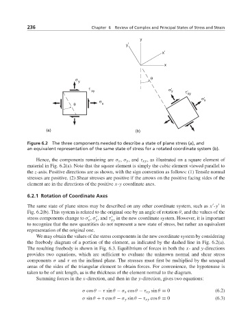
Figure 6.2 The three components needed to describe a state of plane stress (a), and
an equivalent representation of the same state of stress for a rotated coordinate system (b).
Hence, the components remaining are σ x , σ y , and τ xy , as illustrated on a square element of
material in Fig. 6.2(a). Note that the square element is simply the cubic element viewed parallel to
the z-axis. Positive directions are as shown, with the sign convention as follows: (1) Tensile normal
stresses are positive. (2) Shear stresses are positive if the arrows on the positive facing sides of the
element are in the directions of the positive x-y coordinate axes.
6.2.1 Rotation of Coordinate Axes
The same state of plane stress may be described on any other coordinate system, such as x -y in
Fig. 6.2(b). This system is related to the original one by an angle of rotation θ, and the values of the
stress components change to σ , σ , and τ xy in the new coordinate system. However, it is important
y
x
to recognize that the new quantities do not represent a new state of stress, but rather an equivalent
representation of the original one.
We may obtain the values of the stress components in the new coordinate system by considering
the freebody diagram of a portion of the element, as indicated by the dashed line in Fig. 6.2(a).
The resulting freebody is shown in Fig. 6.3. Equilibrium of forces in both the x- and y-directions
provides two equations, which are sufficient to evaluate the unknown normal and shear stress
components σ and τ on the inclined plane. The stresses must first be multiplied by the unequal
areas of the sides of the triangular element to obtain forces. For convenience, the hypotenuse is
taken to be of unit length, as is the thickness of the element normal to the diagram.
Summing forces in the x-direction, and then in the y-direction, gives two equations:
σ cos θ − τ sin θ − σ x cos θ − τ xy sin θ = 0 (6.2)
σ sin θ + τ cos θ − σ y sin θ − τ xy cos θ = 0 (6.3)