
Page 237 - Mechanical Behavior of Materials
P. 237
238 Chapter 6 Review of Complex and Principal States of Stress and Strain
σ y
τ xy 45 o
(a) σ x σ
σ τ3 θ n 2
θ s
σ
1
σ τ3
(b)
(c)
τ
3
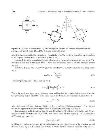
Figure 6.4 A state of plane stress (a), and the special coordinate systems that contain the
principal normal stresses (b) and the principal shear stress (c).
Also, the shear stress at the θ n orientation is found to be zero. The resulting equivalent representation
of the original state of stress is illustrated by Fig. 6.4(b).
As noted, the shear stress is zero on the planes where the principal normal stresses occur. The
converse is also true: If the shear stress is zero, then the normal stresses are the principal normal
stresses.
Similarly, Eq. 6.5 and dτ/dθ = 0 give the coordinate axes rotation for the maximum shear
stress:
σ x − σ y
tan 2θ s =− (6.8)
2τ xy
The corresponding shear stress from Eq. 6.5 is
2
σ x − σ y 2
τ 3 = + τ xy (6.9)
2
This is the maximum shear stress in the x-y plane and is called the principal shear stress. Also, the
two orthogonal planes where this shear stress occurs are found to have the same normal stress of
σ x + σ y
σ τ3 = (6.10)
2
where the special subscript indicates that this is the normal stress that accompanies τ 3 . This second
equivalent representation of the original state of stress is illustrated by Fig. 6.4(c).
Equations 6.6 and 6.8 indicate that 2θ n and 2θ s differ by 90 . Hence, if both 2θ n and 2θ s are
◦
◦
considered to be limited to the range ±90 , then one of these must be negative—that is, clockwise
(CW)—and we can write
|θ n − θ s | = 45 ◦ (6.11)
In addition, τ 3 and the accompanying normal stress can be expressed in terms of the principal normal
stresses σ 1 and σ 2 by substituting Eqs. 6.9 and 6.10 into the two relations represented by Eq. 6.7.