Page 241 - Mechanical Behavior of Materials
P. 241

242                       Chapter 6  Review of Complex and Principal States of Stress and Strain

                                       τ
                                                             (σ   , τ  )
                                                             (σ   , τ  )
                                                              τ3 τ3  3 3
                                                  (σ  , τ   )
                                                   y  xy
                 Tension (+)                                    D
                                                 '
                                               '
                                             (σ  , τ    )  A
                                                 xy
                                               y
                                                        B
                                                                      2θ      (σ  , 0)
                                                      C                 n      1       σ
                                      0      (σ  , 0)
                                               2
                                                                         2θ
                Compression (–)                              2θ s           (σ  , –τ    )
                                                                                  '
                                                                              '
                                                                                  xy
                                                                              x
                                                                        (σ  , –τ )
                                                                          x  xy
                                                            (σ   , –τ )
                                                              τ3  3
                             CW(+)       CCW(–)

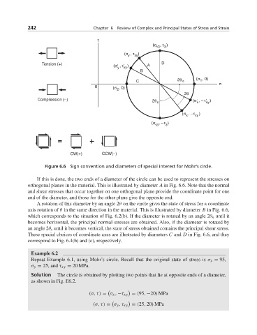
                   Figure 6.6 Sign convention and diameters of special interest for Mohr’s circle.

               If this is done, the two ends of a diameter of the circle can be used to represent the stresses on
            orthogonal planes in the material. This is illustrated by diameter A in Fig. 6.6. Note that the normal
            and shear stresses that occur together on one orthogonal plane provide the coordinate point for one
            end of the diameter, and those for the other plane give the opposite end.
               A rotation of this diameter by an angle 2θ on the circle gives the state of stress for a coordinate
            axis rotation of θ in the same direction in the material. This is illustrated by diameter B in Fig. 6.6,
            which corresponds to the situation of Fig. 6.2(b). If the diameter is rotated by an angle 2θ n until it
            becomes horizontal, the principal normal stresses are obtained. Also, if the diameter is rotated by
            an angle 2θ s until it becomes vertical, the state of stress obtained contains the principal shear stress.
            These special choices of coordinate axes are illustrated by diameters C and D in Fig. 6.6, and they
            correspond to Fig. 6.4(b) and (c), respectively.


             Example 6.2
             Repeat Example 6.1, using Mohr’s circle. Recall that the original state of stress is σ x = 95,
             σ y = 25, and τ xy = 20 MPa.

             Solution  The circle is obtained by plotting two points that lie at opposite ends of a diameter,
             as shown in Fig. E6.2.


                                    (σ, τ) = σ x , −τ xy = (95, −20) MPa

                                     (σ, τ) = σ y ,τ xy = (25, 20) MPa
   236   237   238   239   240   241   242   243   244   245   246