
Page 242 - Mechanical Behavior of Materials
P. 242
Section 6.2 Plane Stress 243
τ, MPa
60
(60, 40.3)
(25, 20)
40.3
20
35 (100.3, 0)
σ, MPa
0 (19.7, 0) 2θ n
2θ s
(95, –20)
(60, –40.3)
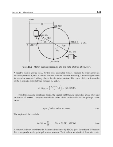
Figure E6.2 Mohr’s circle corresponding to the state of stress of Fig. E6.1.
A negative sign is applied to τ xy for the point associated with σ x , because the shear arrows on
the same planes as σ x tend to cause a counterclockwise rotation. Similarly, a positive sign is used
for τ xy when associated with σ y , due to the clockwise rotation. The center of the circle must lie
on the σ-axis at a point halfway between σ x and σ y :
σ x + σ y
(σ, τ) ctr. = , 0 = (60, 0) MPa
2
From the preceding coordinate points, the shaded right triangle shown has a base of 35 and
an altitude of 20 MPa. The hypotenuse is the radius of the circle and is also the principal shear
stress:
2
2
τ 3 = 35 + 20 = 40.3MPa Ans.
The angle with the σ-axis is
20
tan 2θ n = , 2θ n = 29.74 ◦ (CCW) Ans.
35
A counterclockwise rotation of the diameter of the circle by this 2θ n gives the horizontal diameter
that corresponds to the principal normal stresses. Their values are obtained from the center