
Page 240 - Mechanical Behavior of Materials
P. 240
Section 6.2 Plane Stress 241
τ
σ = σ + σ y
x
τ3
2
(σ , τ )
y
xy
τ
3
σ
0
σ
2 (σ , −τ )
xy
x
σ 1
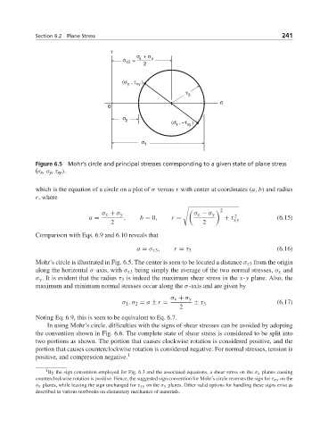
Figure 6.5 Mohr’s circle and principal stresses corresponding to a given state of plane stress
(σ x , σ y , τ xy ).
which is the equation of a circle on a plot of σ versus τ with center at coordinates (a, b) and radius
r, where
2
σ x + σ y σ x − σ y
2
a = , b = 0, r = + τ xy (6.15)
2 2
Comparison with Eqs. 6.9 and 6.10 reveals that
a = σ τ3 , r = τ 3 (6.16)
Mohr’s circle is illustrated in Fig. 6.5. The center is seen to be located a distance σ τ3 from the origin
along the horizontal σ-axis, with σ τ3 being simply the average of the two normal stresses, σ x and
σ y . It is evident that the radius τ 3 is indeed the maximum shear stress in the x-y plane. Also, the
maximum and minimum normal stresses occur along the σ-axis and are given by
σ x + σ y
σ 1 ,σ 2 = a ± r = ± τ 3 (6.17)
2
Noting Eq. 6.9, this is seen to be equivalent to Eq. 6.7.
In using Mohr’s circle, difficulties with the signs of shear stresses can be avoided by adopting
the convention shown in Fig. 6.6. The complete state of shear stress is considered to be split into
two portions as shown. The portion that causes clockwise rotation is considered positive, and the
portion that causes counterclockwise rotation is considered negative. For normal stresses, tension is
positive, and compression negative. 1
1
By the sign convention employed for Fig. 6.3 and the associated equations, a shear stress on the σ x planes causing
counterclockwise rotation is positive. Hence, the suggested sign convention for Mohr’s circle reverses the sign for τ xy on the
σ x planes, while leaving the sign unchanged for τ xy on the σ y planes. Other valid options for handling these signs exist as
described in various textbooks on elementary mechanics of materials.