
Page 301 - Mechanical Behavior of Materials
P. 301
302 Chapter 7 Yielding and Fracture under Combined Stresses
σ
3
τ'
σ σ
θ c 1 3
σ'
τ
μ σ 1
σ 2
τ i
(σ',τ')
2θ
2θ c c τ + μσ = τ i θ c θ c
φ
σ
σ σ 0 σ
3 2 1 fracture planes
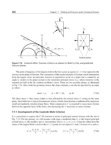
Figure 7.14 Coulomb–Mohr fracture criterion as related to Mohr’s circle, and predicted
fracture planes.
The point of tangency of the largest circle to the line occurs at a point (σ ,τ ) that represents the
stresses on the plane of fracture. The orientation of this predicted plane of fracture can be determined
from the largest circle. In particular, fracture is expected to occur on a plane that is rotated by an
angle θ c relative to the plane normal to the maximum principal stress (σ 1 ), where rotations in the
material are half of the 2θ c rotation on Mohr’s circle. There are two possible planes, as illustrated
in Fig. 7.14. Also, from the geometry shown, the slope constant μ can also be specified by an angle
φ, where
◦
tan φ = μ, φ = 90 − 2θ c (a, b) (7.43)
The shear stress τ that causes failure is thus affected by the normal stress σ acting on the same
plane. Such behavior is logical for materials where a brittle shear fracture is influenced by numerous
small and randomly oriented planar flaws. More compressive σ is expected to cause more friction
between the opposite faces of the flaws, thus increasing the τ necessary to cause fracture.
7.7.1 Development of the Coulomb–Mohr Criterion
It is convenient to express the C–M criterion in terms of principal normal stresses with the aid of
Fig. 7.14. For the present, we will assume (with signs considered) that σ 1 is the largest principal
normal stress, σ 3 the smallest, and σ 2 intermediate; that is, σ 1 ≥ σ 2 ≥ σ 3 . Using the radius from the
center of the largest Mohr’s circle to the (σ , τ ) point, we can express σ and τ in terms of σ 1 and σ 3 :
σ 1 + σ 3 σ 1 − σ 3 σ 1 − σ 3
τ =
σ = + cos 2θ c , sin 2θ c (7.44)
2 2 2