
Page 300 - Mechanical Behavior of Materials
P. 300
Section 7.7 Coulomb–Mohr Fracture Criterion 301
σ , MPa
2
300
σ
max. normal ut
mod. Mohr
σ σ
uc ut σ , MPa
–700 –300 0 300 1
σ i
–300 torsion
Gray cast iron data
σ uc
–700
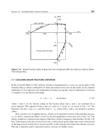
Figure 7.13 Biaxial fracture data of gray cast iron compared with two fracture criteria. (Data
from [Grassi 49].)
7.7 COULOMB–MOHR FRACTURE CRITERION
In the Coulomb–Mohr (C–M) criterion, fracture is hypothesized to occur on a given plane in the
material when a critical combination of shear and normal stress acts on this plane. In the simplest
application of this approach, the mathematical function giving the critical combination of stresses
is assumed to be the linear relationship
(at fracture) (7.42)
|τ| + μσ = τ i
where τ and σ are the stresses acting on the fracture plane and μ and τ i are constants for a
given material. This equation forms a line on a plot of σ versus |τ|, as shown in Fig. 7.14. The
intercept with the τ axis is τ i , and the slope is −μ, where both τ i and μ are defined as positive
values.
Now consider a set of applied stresses, which can be specified in terms of the principal stresses,
σ 1 , σ 2 , and σ 3 , and plot the Mohr’s circles for the principal planes on the same axes as Eq. 7.42. The
failure condition is satisfied if the largest of the three circles is tangent to (just touches) the Eq. 7.42
line. If the largest circle does not touch the line, a safety factor greater than unity exists. Intersection
of the largest circle and the line is not permissible, as this indicates that failure has already occurred.
The line is therefore said to represent a failure envelope for Mohr’s circle.