
Page 304 - Mechanical Behavior of Materials
P. 304
Section 7.7 Coulomb–Mohr Fracture Criterion 305
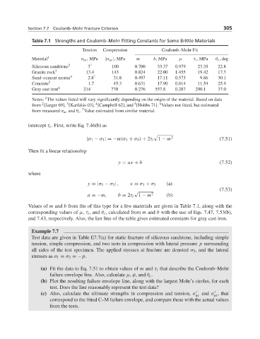
Table 7.1 Strengths and Coulomb–Mohr Fitting Constants for Some Brittle Materials
Tension Compression Coulomb–Mohr Fit
Material 1 σ ut ,MPa |σ uc |,MPa m b,MPa μ τ i ,MPa θ c ,deg
Siliceous sandstone 2 3 7 100 0.700 33.37 0.979 23.35 22.8
Granite rock 3 13.4 143 0.824 22.00 1.455 19.42 17.3
Sand–cement mortar 4 2.8 7 31.8 0.497 17.11 0.573 9.86 30.1
Concrete 5 1.7 45.3 0.631 17.90 0.814 11.54 25.4
Gray cast iron 6 214 770 0.276 557.8 0.287 290.1 37.0
1
Notes: The values listed will vary significantly depending on the origin of the material. Based on data
2
6
5
4
3
from [Jaeger 69], [Karfakis 03], [Campbell 62], and [Hobbs 71]. Values not fitted, but estimated
7
from measured σ uc and θ c . Value estimated from similar material.
intercept τ i . First, write Eq. 7.46(b) as
|σ 1 − σ 3 | =−m(σ 1 + σ 3 ) + 2τ i 1 − m 2 (7.51)
Then fit a linear relationship
y = ax + b (7.52)
where
y = |σ 1 − σ 3 | , x = σ 1 + σ 3 (a)
(7.53)
√
a =−m, b = 2τ i 1 − m 2 (b)
Values of m and b from fits of this type for a few materials are given in Table 7.1, along with the
corresponding values of μ, τ i , and θ c , calculated from m and b with the use of Eqs. 7.47, 7.53(b),
and 7.43, respectively. Also, the last line of the table gives estimated constants for gray cast iron.
Example 7.7
Test data are given in Table E7.7(a) for static fracture of siliceous sandstone, including simple
tension, simple compression, and two tests in compression with lateral pressure p surrounding
all sides of the test specimen. The applied stresses at fracture are denoted σ 3 , and the lateral
stresses as σ 1 = σ 2 =−p.
(a) Fit the data to Eq. 7.51 to obtain values of m and τ i that describe the Coulomb–Mohr
failure envelope line. Also, calculate μ, φ, and θ c .
(b) Plot the resulting failure envelope line, along with the largest Mohr’s circles, for each
test. Does the line reasonably represent the test data?
(c) Also, calculate the ultimate strengths in compression and tension, σ uc and σ , that
ut
correspond to the fitted C–M failure envelope, and compare these with the actual values
from the tests.