
Page 308 - Mechanical Behavior of Materials
P. 308
Section 7.7 Coulomb–Mohr Fracture Criterion 309
σ
3
axis
σ
2
σ = 0
3
σ
1
γ
axis
β
α
α = β = γ
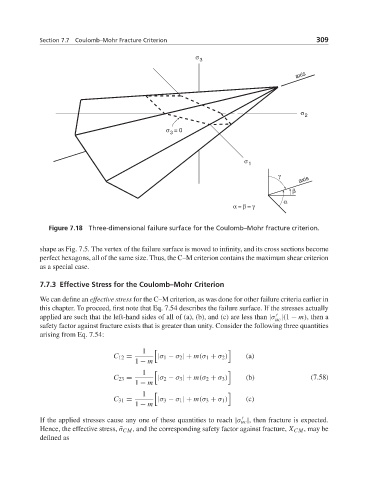
Figure 7.18 Three-dimensional failure surface for the Coulomb–Mohr fracture criterion.
shape as Fig. 7.5. The vertex of the failure surface is moved to infinity, and its cross sections become
perfect hexagons, all of the same size. Thus, the C–M criterion contains the maximum shear criterion
as a special case.
7.7.3 Effective Stress for the Coulomb–Mohr Criterion
We can define an effective stress for the C–M criterion, as was done for other failure criteria earlier in
this chapter. To proceed, first note that Eq. 7.54 describes the failure surface. If the stresses actually
applied are such that the left-hand sides of all of (a), (b), and (c) are less than |σ |(1 − m), then a
uc
safety factor against fracture exists that is greater than unity. Consider the following three quantities
arising from Eq. 7.54:
1 " #
C 12 = |σ 1 − σ 2 | + m(σ 1 + σ 2 ) (a)
1 − m
1 " #
C 23 = |σ 2 − σ 3 | + m(σ 2 + σ 3 ) (b) (7.58)
1 − m
1 " #
C 31 = |σ 3 − σ 1 | + m(σ 3 + σ 1 ) (c)
1 − m
If the applied stresses cause any one of these quantities to reach |σ uc |, then fracture is expected.
Hence, the effective stress, ¯σ CM , and the corresponding safety factor against fracture, X CM , may be
defined as