
Page 312 - Mechanical Behavior of Materials
P. 312
Section 7.8 Modified Mohr Fracture Criterion 313
The intersection of the C–M and the maximum normal stress parts of the M-M failure locus for
biaxial stress occurs at a stress σ i , as shown in Fig. 7.20(a). In particular, there is usually a biaxial
state of stress, σ 1 = σ ut ,σ 2 = σ i ,σ 3 = 0, with σ i negative, where both the C–M and maximum
normal stress criteria are obeyed. Substituting this combination of stresses into Eq. 7.54(a) and
solving for σ i gives
1 + m
σ i =−|σ |+ σ ut (σ ut ≤ σ ) (7.62)
uc
ut
1 − m
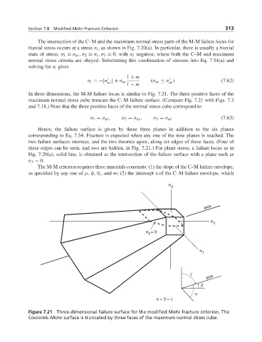
In three dimensions, the M-M failure locus is similar to Fig. 7.21. The three positive faces of the
maximum normal stress cube truncate the C–M failure surface. (Compare Fig. 7.21 with Figs. 7.3
and 7.18.) Note that the three positive faces of the normal stress cube correspond to
σ 1 = σ ut , σ 2 = σ ut , σ 3 = σ ut (7.63)
Hence, the failure surface is given by these three planes in addition to the six planes
corresponding to Eq. 7.54. Fracture is expected when any one of the nine planes is reached. The
two failure surfaces intersect, and the two theories agree, along six edges of these faces. (Four of
these edges can be seen, and two are hidden, in Fig. 7.21.) For plane stress, a failure locus as in
Fig. 7.20(a), solid line, is obtained as the intersection of the failure surface with a plane such as
σ 3 = 0.
The M-M criterion requires three materials constants: (1) the slope of the C–M failure envelope,
as specified by any one of μ, φ, θ c , and m; (2) the intercept τ i of the C–M failure envelope, which
σ
3
axis
σ
2
σ = 0
3
σ
1
γ
axis
β
α
α = β = γ
Figure 7.21 Three-dimensional failure surface for the modified Mohr fracture criterion. The
Coulomb–Mohr surface is truncated by three faces of the maximum normal stress cube.