
Page 72 - Moving the Earth_ The Workbook of Excavation
P. 72
SURVEYS AND MEASUREMENTS
2.22 THE WORK
Obstructions. Buildings, vegetation, and rough ground interfere seriously with primitive instru-
ment techniques and make it more economical to hire an engineer.
Large permanent obstructions require layout of additional lines and angles to work around
them.
Brush clearing for sight lines is laborious and sometimes quite destructive. It is handled by set-
ting up the instrument, pointing it in the desired direction, and directing the cutters so that their
work will be kept close to the line of sight.
In heavy undergrowth a mistake in turning an angle may waste hours of cutting work.
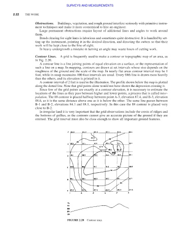
Contour Lines. A grid is frequently used to make a contour or topographic map of an area, as
in Fig. 2.20.
A contour line is a line joining points of equal elevation on a surface, or the representation of
such a line on a map. In mapping, contours are drawn at set intervals whose size depends on the
roughness of the ground and the scale of the map. In nearly flat areas contour interval may be 1
foot, while in steep mountains 100-foot intervals are usual. Every fifth line is drawn more heavily
than the others, and its elevation is printed in it.
A contour interval of 2 feet is used in the illustration. The profile shown below the map is plotted
along the dotted line. Note that grid points alone would not have shown the depression crossing it.
Since few of the grid points are exactly at a contour elevation, it is necessary to estimate the
locations of the lines as they pass between higher and lower points, a process that is called inter-
polation. The 88 contour is placed halfway between point A-3, elevation 87.4, and B-3, elevation
88.6, as it is the same distance above one as it is below the other. The same line passes between
B-1 and B-2, elevations 84.1 and 88.1, respectively. In this case the 88 contour is placed very
close to B-2.
In irregular land it is very important that the grid observations include the crests of ridges and
the bottoms of gullies, as the contours cannot give an accurate picture of the ground if they are
omitted. The grid interval must also be close enough to show all important ground features.
FIGURE 2.20 Contour map.