
Page 71 - Moving the Earth_ The Workbook of Excavation
P. 71
SURVEYS AND MEASUREMENTS
SURVEYS AND MEASUREMENTS 2.21
Elevations are now taken on each peg, preferably doing them a complete line at a time to avoid con-
fusion. The rod reading may be written just above each point. Readings should also be taken on high
and low spots, drain channels, and anything else of interest, and noted in the correct place on the paper.
When the instrument work is finished, the readings are preferably converted to positive numbers
that can be penciled below the points, and the rod reading is crossed out.
This grid sheet can be used for reference for any locations or grading estimates which may be
required, and in drawing contours, profiles, and cross sections.
Grids without Instruments. If no instrument that will turn angles is available, a grid may be laid
out with a tape, and elevations taken with a hand level. A baseline is decided upon, and a tall stake
set at each end. A tape—the longer, the better—is pinned at one end and extended toward the other,
and lined up by sighting across it from one stake to another. The intervals are measured, and the
tape is moved on and lined up again.
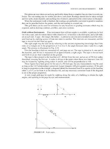
The right angle may be laid out by referring to the ancient engineering knowledge that if the
sides of a triangle are in the proportion of 3 to 4 to 5, the angle between sides 3 and 4 is a right
angle. The process is illustrated in Fig. 2.19.
First the baseline is laid out, measured off, and pegs are set. The tape is pinned at A, one end of
the baseline, and 30 feet is measured off at approximately a right angle. The tape is moved back
and forth in an arc that is marked on the ground.
The tape is then pinned to the baseline at C, 40 feet from the end, and an arc of 50-foot radius
described, crossing the first arc. A stake is driven at the point where these arcs intersect. Line AE
may be located by sighting along stakes A and D, and will be perpendicular to AB.
These figures have been given for the use of a 50-foot tape, but any measurements may be used
as long as the 3:4:5 relationship is preserved. Larger triangles will give greater accuracy. If the grid
is large in proportion to the triangle, a diagonal should be measured from E to a point on the baseline
3
1
either ⁄ 4 or 1 ⁄ 3 as far from A as the distance AE, and any necessary correction made if the diagonal
is not in the proper proportion.
A very rough grid may be made by sighting along the sides of a building to obtain the right
angles, and spotting in the pegs by eye and measurement.
FIGURE 2.19 Right angles.