
Page 70 - Moving the Earth_ The Workbook of Excavation
P. 70
SURVEYS AND MEASUREMENTS
2.20 THE WORK
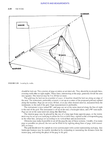
FIGURE 2.18 Locating by stadia.
should be laid out. This consists of pegs or stakes at set intervals. They should be in straight lines,
crossing each other at right angles. These lines, intersecting at the pegs, generally divide the area
into squares. The interval may be 5 to 20 feet or more.
The grid may be laid out in a number of ways. A baseline should be laid out along an edge of
the area. The instrument, preferably a transit, is set up at a corner of the proposed grid and sighted
along the baseline. Pegs are set every 10 feet, or at any other desired interval, measured from the
instrument, to the end of the grid. Tape measurement is preferable.
The instrument is now turned 90°, and pegs are set at the same interval along the line of sight
to the end of the grid. The instrument is set up at the end, a backsight taken, and a 90° turn made.
Pegs are set at the same intervals along this third line.
The interior pegs may be placed by the use of a long tape from opposite pegs, or the instru-
ment may be set up over each peg in either the first or third lines, sighted at the corresponding peg
in the other line, and pegs set according to its vertical hair and measurement.
Obstacles may make it possible to set all the pegs by any of these systems. Usually, if as many
pegs as possible are placed, the rest can be filled in by sighting along lines of pegs, with reason-
able accuracy.
The grid should now be copied on cross-section paper with a point representing each peg. Any
landscape features may be readily sketched in by estimating or measuring the distance from the
nearest peg, and noting the place of the peg in the grid.