
Page 65 - Moving the Earth_ The Workbook of Excavation
P. 65
SURVEYS AND MEASUREMENTS
SURVEYS AND MEASUREMENTS 2.15
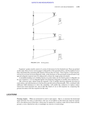
FIGURE 2.13A Setting grades.
Engineers’ grades usually consist of a series of elevations for the finished road. These are plotted
on the same sheet of cross-section paper as the profile of the ground surface, and the depth of cut or
fill is determined by measuring the distance between the two lines. These figures, if used directly,
will not be accurate for most subgrade work, as the thickness of the pavement or gravel and of any
special subgrade material must be subtracted to obtain the rough grade elevations.
A misunderstanding as to whether figures on grade stakes are for finish grade or subgrade can
be very expensive. Use of subgrade figures for preparing subgrades is usually most satisfactory.
The contractor may obtain from the engineer a list or profile showing subgrade elevation at
each station, and information as to the location and elevation of benchmarks. This, combined with
sufficient field references to show the centerline, will enable the contractor to replace stakes
which have been knocked out, and to find the depth of cut or fill required, by comparing the
ground elevation with that required for the road.
LOCATIONS
Turning Angles. When an instrument is used to turn angles—that is, to measure the horizontal
angle between two lines or directions—the axis of revolution of the telescope must be exactly
above the intersection of the lines, which may be marked by a nail in a stake driven flush with the
ground, a cross chiseled in rock, or markings on concrete or metal plugs.