
Page 62 - Moving the Earth_ The Workbook of Excavation
P. 62
SURVEYS AND MEASUREMENTS
2.12 THE WORK
If the numbers become illegible, they can be fixed for rough work by measuring and marking
the feet, and perhaps some fine divisions, with paint. A broken tape can be repaired by means of
a splint and two rivets.
Cloth tapes stretch readily, and are not accurate enough for even rough use. Metallic tapes,
composed of cloth with interwoven wires, are variable in quality and resistance to stretching. If
used, they should be checked occasionally by a good steel tape.
Steel tapes change length with temperature and stretch under tension, but these changes are so
small that they can be ignored in open work.
Tapes must be held level, or very nearly so, on slopes, as engineers’ land measurements refer
to distances on a horizontal plane. The downhill end of the tape may be placed exactly above the
desired point by use of a plumb bob, or by dropping pebbles from the tape end.
Centerlines usually include angles or curves. If the former, measurements must be made to and
from the angle point, rather than by a shortcut. Gradual curves may be measured in a series of chords
(straight lines beginning and ending in the curve). Sharper curves may require a reduction in the
length of the chords, as from 100 to 50, or 25 or even 10 feet. The difference in length between the chord
and the arc of the curve may be readily found by laying the tape along the curve from one chord point
to another; or measuring a distance along it in very short chords, then measuring the distance between
the two points directly. If no significant difference is found, the chords are not too long.
Tapes are best suited to two-person use. However, the loop on the zero end can be anchored in
dirt with a screwdriver, and to stakes with a pushpin or thumbtack, and measurements made by
one person.
Ground measurements may also be made with the rod, with a short rule, a stick of known
length, or for very rough work, by pacing.
Stadia. If the instrument is equipped with stadia hairs, it may be used to measure distance as
well as elevation. If the stadia ratio is the usual 1 to 100, and the rod is marked in feet, tenths and
hundredths of feet, each tenth visible between the stadia hairs indicates a distance of 10 feet from
the center of the telescope to the rod. Six tenths would mean a distance of 60 feet, a foot would
mean 100 feet. This distance may be noted at the same time as the crosshair reading.
1
If the rod is marked in feet, inches, and eighths of inches, each inch indicates a distance of 8 ⁄ 3
feet, each foot 100 feet.
If a distance is to be measured off, the rod is held at increasing distances from the instrument
in response to signals, until the proper number of markings shows between the stadia hairs.
The rod should be held perpendicular to the line of sight. The correct angle can be found by
pivoting it slowly toward and away from the instrument, until the minimum reading is obtained.
Turning Points. If elevations are to be taken for any points above the crosshair, the instrument
must be picked up and reset at a higher elevation. It must be located so that it can take a reading
on at least one point that was taken from the old setting. This point (turning or transfer point) is
preferably one of the higher elevations (low readings) taken, and should lie between the two
instrument locations. It is best taken from the top of a firm stake, or a knob or a well-marked spot
on rock or hard ground, so that the rod set on it will be at exactly the same height at the second
reading as at the first. Accuracy in reading at the turning point is very important, as any error made
will persist through the rest of the survey. Amateurs are advised to use two turning points with
each move, as mistakes in reading or in arithmetic should then show up immediately.
The new instrument elevation (abbreviated H.I. for height of instrument) is found by subtract-
ing the smaller reading from the larger one for each turning point, and, in an uphill move, adding
the result to the first elevation of the instrument.
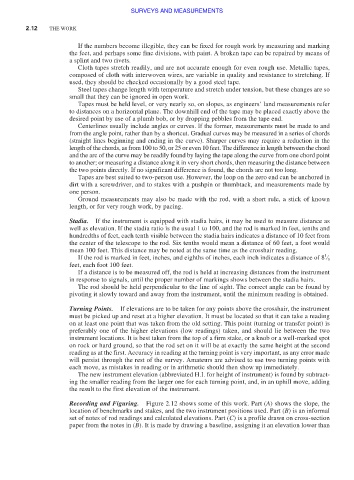
Recording and Figuring. Figure 2.12 shows some of this work. Part (A) shows the slope, the
location of benchmarks and stakes, and the two instrument positions used. Part (B) is an informal
set of notes of rod readings and calculated elevations. Part (C) is a profile drawn on cross-section
paper from the notes in (B). It is made by drawing a baseline, assigning it an elevation lower than