
Page 117 - Petroleum Production Engineering, A Computer-Assisted Approach
P. 117
Guo, Boyun / Computer Assited Petroleum Production Engg 0750682701_chap09 Final Proof page 111 21.12.2006 2:16pm
WELL TUBING 9/111
Consider the case in which we have only tensile axial loads, Case 2: Axial tension stress (s 1 > 0) and burst pressure
and compressive pressure on the outside of the tubing, (s 2 > 0)
then Eq. (9.12) reduces to
Case 3: Axial compression stress (s 1 < 0) and collapse
n o pressure (s 2 < 0)
1
2
2
2
ð
ð
s ¼ ð s 1 s 2 Þ þ s 2 Þ þ s 1 Þ 2 (9:13)
e 2 Case 4: Axial compression stress (s 1 < 0) and burst pres-
sure (s 2 > 0)
or
2
2
2
s ¼ s s 1 s 2 þ s : (9:14) Example Problem 9.1 Calculate the collapse resistance
2
e
1
7
for a section of 2 ⁄ 8 in. API 6.40 lb/ft, Grade J-55, non-
Further, we can define upset tubing near the surface of a 10,000-ft string
suspended from the surface in a well that is producing gas.
W
s 1 ¼ Solution Appendix B shows an inner diameter of tubing
A (9:15) of 2.441 in., therefore,
s 2 p cc
¼ ;
Y m p c t ¼ (2:875 2:441)=2 ¼ 0:217 in:
where
D 2:875
¼ ¼ 13:25
Y m ¼ minimum yield stress t 0:217
p cc ¼ the collapse pressure corrected for axial load 13:25 1
p c ¼ the collapse pressure with no axial load. p c ¼ 2(55; 000) ¼ 7,675:3 psi,
(13:25) 2
s e ¼ Y m which is consistent with the rounded value of 7,680 psi
Thus, Eq. (9.14) becomes listed in Appendix B.
A ¼ pt(D t) ¼ p(0:217)(2:875 0:217) ¼ 1:812 in: 2
2 2
2
Y ¼ W þ W p cc Y m þ p cc Y m 2 (9:16) 6:40(10,000)
m
A A p c p c S A ¼ ¼ 35,320 psi:
1:812
2 2
p cc W p cc W Using Eq. (9.19), we get
þ þ 1 ¼ 0: (9:17) 8 s ffiffiffiffiffiffiffiffiffiffiffiffiffiffiffiffiffiffiffiffiffiffiffiffiffiffiffiffiffiffiffiffiffiffiffiffiffiffiffiffi 9
p c AY m p c AY m < 35,320 2 35; 320 =
p cc ¼ 7675:3 1 0:75 0:5
We can solve Eq. (9.17) for the term p cc . This yields : 55,000 55,000 ;
p c
r ffiffiffiffiffiffiffiffiffiffiffiffiffiffiffiffiffiffiffiffiffiffiffiffiffiffiffiffiffiffiffiffiffiffiffiffiffiffiffiffiffiffiffiffiffiffiffiffi ¼ 3,914:5 psi:
2
2
W W 4 W þ 4
p cc AY m AY m AY m
¼ (9:18)
p c 2
8 s ffiffiffiffiffiffiffiffiffiffiffiffiffiffiffiffiffiffiffiffiffiffiffiffiffiffiffiffiffiffiffiffiffi 9
< 2 =
S A S A 9.3 Tubing Design
p cc ¼ p c 1 0:75 0:5 , (9:19)
: Y m Y m ; Tubing design should consider tubing failure due to
tension, collapse, and burst loads under various well
where S A ¼ W is axial stress at any point in the tubing operating conditions. Forces affecting tubing strings in-
A
string. clude the following:
In Eq. (9.19), it can be seen that as W (or S A ) increases, 1. Axial tension due to weight of tubing and compression
the corrected collapse pressure resistance decreases (from due to buoyancy
the nonaxial load case). 2. External pressure (completion fluids, oil, gas, forma-
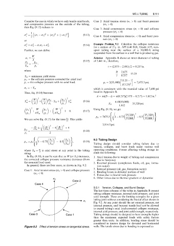
In general, there are four cases, as shown in Fig. 9.2: tion water)
3. Internal pressure (oil, gas, formation water)
Case 1: Axial tension stress (s 1 > 0) and collapse pressure
(s 2 < 0) 4. Bending forces in deviated portion of well
5. Forces due to lateral rock pressure
s 2 6. Other forces due to thermal gradient or dynamics
Case 2
Case 4
9.3.1 Tension, Collapse, and Burst Design
The last three columns of the tables in Appendix B present
tubing collapse resistance, internal yield pressure, and joint
yield strength. These are the limiting strengths for a given
tubing joint without considering the biaxial effect shown in
s 1
Fig. 9.2. At any point should the net external pressure, net
internal pressure, and buoyant tensile load not be allowed
to exceed tubing’s axial load-corrected collapse resistance,
internal yield pressure, and joint yield strength, respectively.
Case 3 Case 1 Tubing strings should be designed to have strengths higher
than the maximum expected loads with safety factors
greater than unity. In addition, bending stress should be
considered in tension design for deviated and horizontal
Figure 9.2 Effect of tension stress on tangential stress. wells. The tensile stress due to bending is expressed as