
Page 119 - Petroleum Production Engineering, A Computer-Assisted Approach
P. 119
Guo, Boyun / Computer Assited Petroleum Production Engg 0750682701_chap09 Final Proof page 113 21.12.2006 2:16pm
WELL TUBING 9/113
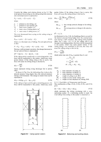
Consider the tubing–pack relation shown in Fig. 9.3. The packer failure. If the tubing string is free to move, this
total upward force acting on the tubing string from internal force will cause the tubing string to shorten by
and external pressures is expressed as
2
2L Dp i avg R D p o avg
0 0
F up ¼ p i (A p A ) þ p o (A o A ), (9:24) DL B ¼ 10 8 R 1 , (9:30)
i
2
o
where
where
p i ¼ pressure in the tubing, psi Dp i avg ¼ the average pressure change in the tubing,
p o ¼ pressure in the annulus, psi psi
A p ¼ inner area of packer, in: 2
0 2 Dp o avg ¼ the average pressure change in the annulus,
A i ¼ inner area of tubing sleeve, in: psi
0 2
A o ¼ outer area of tubing sleeve, in:
2
R ¼ A o =A i :
The total downward force acting on the tubing string is
expressed as As illustrated in Fig. 9.4b, the buckling effect is caused by
the internal pressure being higher than the external pres-
0 0
F down ¼ p i (A i A ) þ p o (A p A ), (9:25) sure during a well treatment. The tubing string buckles
o
i
where A i is the inner area of tubing. The net upward force when F BK ¼ A p (p i p o ) > 0. If the tubing end is set
is then through a restraining packer, this force will be transmitted
to the packer, which may cause packer failure. If the
F ¼ F up F down ¼ p i (A p A i ) p o (A p A o ): (9:26) tubing string is not restrained at bottom, this force will
cause the tubing string to shorten by
During a well treatment operation, the change (increase) in
2
2
the net upward force is expressed as r F BK
DL BK ¼ , (9:31)
8EIW
DF ¼ [Dp i (A p A i ) Dp o (A p A o )]: (9:27)
which holds true only if F BK is greater than 0, and
If the tubing string is anchored to a restraining packer, this
D ci D i
force will be transmitted to the packer, which may cause r ¼
packer failure. If the tubing string is free to move, this p 2
4
4
force will cause the tubing string to shorten by I ¼ (D D )
64 o i
LDF W ¼ W air þ W fi W fo ,
DL P ¼ , (9:28)
AE
where
which represents tubing string shrinkage due to piston
effect. D ci ¼ inner diameter of casing, in.
As shown in Fig. 9.4a, the ballooning effect is due to the D i ¼ inner diameter of tubing, in.
internal pressure being higher than the external pressure D o ¼ outer diameter of tubing, in.
during a well treatment. The change in tensile force can be W air ¼ weight of tubing in air, lb/ft
expressed as W ft ¼ weight of fluid inside tubing, lb/ft
¼ weight of fluid displaced by tubing, lb/ft.
W fo
DF B ¼ 0:6[Dp i avg A i Dp o avg A o ]: (9:29)
If the tubing string is set through a restraining packer, this 9.3.3.3 Total Effect of Temperature and Pressure
force will be transmitted to the packer, which may cause The combination of Eqs. (9.22), (9.28), (9.30), and (9.31)
gives
A o DL ¼ DL T þ DL P þ DL B þ DL BK , (9:32)
which represents the tubing shortening with a non-
A i restraining packer. If a restraining packer is used, the
total tubing force acting on the packer is expressed as
p i p o
A i
A
o
A p
A c
(a) (b)
Figure 9.3 Tubing–packer relation. Figure 9.4 Ballooning and buckling effects.