
Page 123 - Petroleum Production Engineering, A Computer-Assisted Approach
P. 123
Guo, Boyun / Computer Assited Petroleum Production Engg 0750682701_chap10 Final Proof page 118 4.1.2007 8:26pm Compositor Name: SJoearun
10/118 EQUIPMENT DESIGN AND SELECTION
10.1 Introduction coalesce, and collect to form larger droplets that will then
drain back to the liquid section in the bottom of the sep-
Oil and gas produced from wells are normally complex
mixtures of hundreds of different compounds. A typical arator. A stainless steel woven-wire mesh mist eliminator
well stream is a turbulent mixture of oil, gas, water, and can remove up to 99.9% of the entrained liquids from the
sometimes solid particles. The well stream should be pro- gas stream. Cane mist eliminators can be used in areas
cessed as soon as possible after bringing it to the surface. where there is entrained solid material in the gas phase
Field separation processes fall into two categories: that may collect and plug a wire mesh mist eliminator.
(1) separation of oil, water, and gas; and (2) dehydration
that removes condensable water vapor and other undesirable 10.2.2 Types of Separators
compounds, such as hydrogen sulfide or carbon dioxide. Three types of separators are generally available from
This chapter focuses on the principles of separation manufacturers: vertical, horizontal, and spherical separ-
and dehydration and selection of required separators and ators. Horizontal separators are further classified into
dehydrators. two categories: single tube and double tube. Each type of
separator has specific advantages and limitations. Selec-
tion of separator type is based on several factors including
characteristics of production steam to be treated, floor
10.2 Separation System
space availability at the facility site, transportation, and
Separation of well stream gas from free liquids is the first cost.
and most critical stage of field-processing operations.
Composition of the fluid mixture and pressure determine
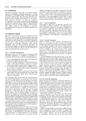
what type and size of separator are required. Separators 10.2.2.1 Vertical Separators
are also used in other locations such as upstream and Figure 10.1 shows a vertical separator. The inlet diverter
downstream of compressors, dehydration units, and gas baffle is a centrifugal inlet device making the incoming
sweetening units. At these locations, separators are stream spin around. This action forces the liquid droplets
referred to as scrubbers, knockouts, and free liquid knock- to stay together and fall to the bottom of the separator
outs. All these vessels are used for the same purpose: to along the separator wall due to gravity. Sufficient surge
separate free liquids from the gas stream. room is available in the settling section of the vertical
separator to handle slugs of liquid without carryover to
the gas outlet. A mist eliminator or extractor near the gas
10.2.1 Principles of Separation outlet allows the entrained liquid in the gas to be almost
Separators work on the basis of gravity segregation and/or eliminated.
centrifugal segregation. A separator is normally con- Vertical separators are often used to treat low to inter-
structed in such a way that it has the following features:
mediate gas–oil ratio well streams and streams with rela-
1. It has a centrifugal inlet device where the primary sep- tively large slugs of liquid. They handle greater slugs of
aration of the liquid and gas is made. liquid without carryover to the gas outlet, and the action
2. It provides a large settling section of sufficient height or of the liquid level control is not as critical. Vertical sep-
length to allow liquid droplets to settle out of the gas arators occupy less floor space, which is important for
stream with adequate surge room for slugs of liquid. facility sites such as those on offshore platforms where
3. It is equipped with a mist extractor or eliminator near space is limited. Because of the large vertical distance
the gas outlet to coalesce small particles of liquid that between the liquid level and the gas outlet, the chance for
do not settle out by gravity. liquid to revaporize into the gas phase is limited. However,
4. It allows adequate controls consisting of level control, because of the natural upward flow of gas in a vertical
liquid dump valve, gas backpressure valve, safety relief separator against the falling droplets of liquid, adequate
valve, pressure gauge, gauge glass, instrument gas separator diameter is required. Vertical separators are more
regulator, and piping. costly to fabricate and ship in skid-mounted assemblies.
The centrifugal inlet device makes the incoming stream
spin around. Depending on the mixture flow rate, the reac- 10.2.2.2 Horizontal Separators
tion force from the separator wall can generate a centripetal Figure 10.2 presents a sketch of a horizontal separator. In
acceleration of up to 500 times the gravitational acceler- horizontal separators, gas flows horizontally while liquid
ation. This action forces the liquid droplets together where droplets fall toward the liquid surface. The moisture gas
they fall to the bottom of the separator into the settling flows in the baffle surface and forms a liquid film that is
section. The settling section in a separator allows the tur- drained away to the liquid section of the separator. The
bulence of the fluid stream to subside and the liquid drop- baffles need to be longer than the distance of liquid trajec-
lets to fall to the bottom of the vessel due to gravity tory travel. The liquid-level control placement is more
segregation. A large open space in the vessel is required critical in a horizontal separator than in a vertical sep-
for this purpose. Use of internal baffling or plates may arator because of limited surge space.
produce more liquid to be discharged from the separator. Horizontal separators are usually the first choice
However, the product may not be stable because of the light because of their low costs. They are almost widely used
ends entrained in it. Sufficient surge room is essential in the for high gas–oil ratio well streams, foaming well streams,
settling section to handle slugs of liquid without carryover or liquid-from-liquid separation. They have much greater
to the gas outlet. This can be achieved by placing the liquid gas–liquid interface because of a large, long, baffled gas-
level control in the separator, which in turn determines the separation section. Horizontal separators are easier to
liquid level. The amount of surge room required depends on skid-mount and service and require less piping for field
the surge level of the production steam and the separator connections. Individual separators can be stacked easily
size used for a particular application. into stage-separation assemblies to minimize space re-
Small liquid droplets that do not settle out of the gas quirements.
stream due to little gravity difference between them and the Figure 10.3 demonstrates a horizontal double-tube sep-
gas phase tend to be entrained and pass out of the separator arator consisting of two tube sections. The upper tube
with the gas. A mist eliminator or extractor near the gas section is filled with baffles, gas flows straight through
outlet allows this to be almost eliminated. The small liquid and at higher velocities, and the incoming free liquid
droplets will hit the eliminator or extractor surfaces, is immediately drained away from the upper tube