
Page 126 - Petroleum Production Engineering, A Computer-Assisted Approach
P. 126
Guo, Boyun / Computer Assited Petroleum Production Engg 0750682701_chap10 Final Proof page 121 4.1.2007 8:26pm Compositor Name: SJoearun
SEPARATION SYSTEMS 10/121
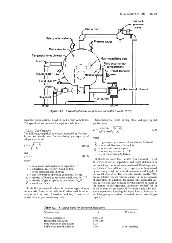
Figure 10.5 A typical spherical low-pressure separator (Sivalls, 1977).
separator specifications based on well stream conditions. Substituting Eq. (10.1) into Eq. (10.2) and applying real
The specifications are used for separator selections. gas law gives
s ffiffiffiffiffiffiffiffiffiffiffiffiffiffiffiffi
2
2:4D Kp r L r g
10.2.4.1 Gas Capacity q st ¼ z(T þ 460) , (10:3)
The following empirical equations proposed by Souders– r g
Brown are widely used for calculating gas capacity of where
oil/gas separators:
s ffiffiffiffiffiffiffiffiffiffiffiffiffiffiffiffi q st ¼ gas capacity at standard conditions, MMscfd
r L r g
v ¼ K (10:1) D ¼ internal diameter of vessel, ft
p ¼ operation pressure, psia
r g
T ¼ operating temperature, 8F
and
z ¼ gas compressibility factor
q ¼ Av, (10:2)
It should be noted that Eq. (10.3) is empirical. Height
where
differences in vertical separators and length differences in
A ¼ total cross-sectional area of separator, ft 2 horizontal separators are not considered. Field experience
v ¼ superficial gas velocity based on total has indicated that additional gas capacity can be obtained
cross-sectional area A, ft/sec by increasing height of vertical separators and length of
3
q ¼ gas flow rate at operating conditions, ft =sec horizontal separators. The separator charts (Sivalls, 1977;
r L ¼ density of liquid at operating conditions, lb m =ft 3 Ikoku, 1984) give more realistic values for the gas capacity
r g ¼ density of gas at operating conditions, lb m =ft 3 of separators. In addition, for single-tube horizontal ves-
K ¼ empirical factor sels, corrections must be made for the amount of liquid in
the bottom of the separator. Although one-half full of
Table 10.1 presents K values for various types of sep- liquid is more or less standard for most single-tube hori-
arators. Also listed in the table are K values used for other zontal separators, lowering the liquid level to increase the
designs such as mist eliminators and trayed towers in available gas space within the vessel can increase the gas
dehydration or gas sweetening units. capacity.
Table 10.1 K Values Used for Selecting Separators
Separator type K Remarks
Vertical separators 0.06–0.35
Horizontal separators 0.40–0.50
Wire mesh mist eliminators 0.35
Bubble cap trayed columns 0.16 24-in. spacing