
Page 129 - Petroleum Production Engineering, A Computer-Assisted Approach
P. 129
Guo, Boyun / Computer Assited Petroleum Production Engg 0750682701_chap10 Final Proof page 124 4.1.2007 8:26pm Compositor Name: SJoearun
10/124 EQUIPMENT DESIGN AND SELECTION
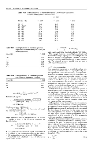
Table 10.6 Settling Volumes of Standard Horizontal Low-Pressure Separators
(125 psi working pressure)(Continued )
V L (bbl)
Size (D L) 1 ⁄ 2 Full 1 ⁄ 3 Full 1 ⁄ 4 Full
00 0
30 5 2.48 1.43 0.94
00 0
30 71=2 3.54 2.04 1.36
00 0
30 10 4.59 2.66 1.77
00 0
36 10 6.71 3.88 2.59
00 0
36 15 9.76 5.66 3.79
00 0
48 10 12.24 7.07 4.71
00 0
48 15 17.72 10.26 6.85
00 0
60 10 19.50 11.24 7.47
00 0
60 15 28.06 16.23 10.82
00 0
60 20 36.63 21.21 14.16
Table 10.7 Settling Volumes of Standard Spherical 1440(0:61)
High-Pressure Separators (230–3,000 psi q L ¼ 1:0 ¼ 878 bbl=day,
working pressure)
which again is much higher than the liquid load of 100 bbl/day.
Size (OD) V L (bbl) This example illustrates a case of high gas/oil ratio well
streams where the gas capacity is the controlling factor for
24’’ 0.15 separator selection. It suggests that a smaller horizontal
30’’ 0.30 separator would be required and would be more econom-
36’’ 0.54 ical. The selected separator should have at least a
42’’ 0.88 1,000 psig working pressure.
48’’ 1.33
60’’ 2.20
10.2.5 Stage separation
Stage separation is a process in which hydrocarbon mix-
tures are separated into vapor and liquid phases by mul-
tiple equilibrium flashes at consecutively lower pressures.
A two-stage separation requires one separator and a stor-
Table 10.8 Settling Volumes of Standard Spherical age tank, and a three-stage separation requires two sep-
Low-Pressure Separators (125 psi) arators and a storage tank. The storage tank is always
Size (OD) V L (bbl) counted as the final stage of vapor/liquid separation.
Stage separation reduces the pressure a little at a time, in
41’’ 0.77 steps or stages, resulting in a more stable stock-tank liquid.
46’’ 1.02 Usually a stable stock-tank liquid can be obtained by a
54’’ 1.60 stage separation of not more than four stages.
In high-pressure gas-condensate separation systems, a
stepwise reduction of the pressure on the liquid condensate
141:5 can significantly increase the recovery of stock-tank
3
r L ¼ 62:4 ¼ 46:11 lb m =ft :
131:5 þ 60 liquids. Prediction of the performance of the various sep-
arators in a multistage separation system can be carried
Equation (10.3) gives
r ffiffiffiffiffiffiffiffiffiffiffiffiffiffiffiffiffiffiffiffiffiffiffiffiffiffi out with compositional computer models using the initial
2
(2:4)(20=12) (0:205)(800) 46:11 3:38 well stream composition and the operating temperatures
q st ¼ and pressures of the various stages.
(0:8427)(80 þ 460) 3:38
Although three to four stages of separation theoretically
¼ 8:70 MMscfd: increase the liquid recovery over a two-stage separation,
the incremental liquid recovery rarely pays out the cost of
Sivalls’s chart gives 5.4 MMscfd.
1
From Table 10.3, a 20-in. 7 ⁄ 2 -ft separator will handle the additional separators. It has been generally recognized
the following liquid capacity: that two stages of separation plus the stock tank are
practically optimum. The increase in liquid recovery for
1440(0:65)
q L ¼ ¼ 936 bbl=day, two-stage separation over single-stage separation usually
1:0 varies from 2 to 12%, although 20 to 25% increases in
which is much higher than the liquid load of 100 bbl/day. liquid recoveries have been reported.
Consider a 16-in. 5-ft horizontal separator and The first-stage separator operating pressure is generally
Eq. (10.3) gives determined by the flowline pressure and operating charac-
r ffiffiffiffiffiffiffiffiffiffiffiffiffiffiffiffiffiffiffiffiffiffiffiffi teristics of the well. The pressure usually ranges from
2
(2:4)(16=12) (0:45)(800) 46:11 ---3:38 600 to 1,200 psi. In situations in which the flowline pres-
q st ¼
(0:8427)(80 þ 460) 3:38 sure is greater than 600 psi, it is practical to let the first-
stage separator ride the line or operate at the flowline
¼ 12:22 MMscfd:
pressure. Pressures at low-stage separations can be deter-
If the separator is one-half full of liquid, it can still treat mined based on equal pressure ratios between the stages
6.11 MMscfd of gas. Sivalls’s chart indicates that a 16-in. (Campbell, 1976):
5-ft horizontal separator will handle 5.1 MMscfd. 1
p 1 N st
From Table 10.5, a half-full, 16-in. 5-ft horizontal R p ¼ , (10:5)
separator will handle p s