
Page 132 - Petroleum Production Engineering, A Computer-Assisted Approach
P. 132
Guo, Boyun / Computer Assited Petroleum Production Engg 0750682701_chap10 Final Proof page 127 4.1.2007 8:26pm Compositor Name: SJoearun
SEPARATION SYSTEMS 10/127
. Space adsorbents degenerate with use and require effective of the glycols because of its superior dew-point
replacement depression, operating cost, and operation reliability. TEG
has been successfully used to dehydrate sweet and sour
Dehydrating tower must be regenerated and cooled for natural gases over wide ranges of operating conditions.
operation before another tower approaches exhaustion. Dew-point depression of 40–1408F can be achieved at a
The maximum allowable time on dehydration gradually gas pressure ranging from 25 to 2,500 psig and gas tem-
shortens because desiccant loses capacity with use. perature between 40 and 1608F. The dew-point depression
Although this type of dehydrator has high adaptability
to sudden load changes, sudden pressure surges should be obtained depends on the equilibrium dew-point tempera-
avoided because they may upset the desiccant bed and ture for a given TEG concentration and contact tempera-
channel the gas stream resulting in poor dehydration. If a ture. Increased glycol viscosity may cause problems at lower
plant is operated above its rated capacity, high-pressure contact temperature. Thus, heating of the natural gas may
loss may introduce some attrition to occur. Attrition be desirable. Very hot gas streams are often cooled before
causes fines, which may in turn cause excessive pressure dehydration to prevent vaporization of TEG.
loss and result in loss of capacity. The feeding-in gas must be cleaned to remove all liquid
Replacing the desiccant should be scheduled and com- water and hydrocarbons, wax, sand, drilling muds, and
pleted ahead of the operating season. To maintain con- other impurities. These substances can cause severe foam-
tinuous operation, this may require discarding the ing, flooding, higher glycol losses, poor efficiency, and
desiccant before its normal operating life is reached. To increased maintenance in the dehydration tower or ab-
cut operating costs, the inlet part of the tower can be sorber. These impurities can be removed using an efficient
recharged and the remainder of the desiccant retained scrubber, separator, or even a filter separator for very
because it may still possess some useful life. Additional contaminated gases. Methanol, injected at the wellhead
as hydrate inhibitor, can cause several problems for glycol
service life of the desiccant may be obtained if the direction dehydration plants. It increases the heat requirements of
of gas flow is reversed at a time when the tower would the glycol regeneration system. Slugs of liquid methanol
normally be recharged.
can cause flooding in the absorber. Methanol vapor vented
to the atmosphere with the water vapor from the regener-
10.3.2.3 Dehydration by Absorption ation system is hazardous and should be recovered or
Water vapor is removed from the gas by intimate contact vented at nonhazardous concentrations.
with a hygroscopic liquid desiccant in absorption dehydra-
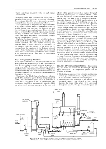
tion. The contacting is usually achieved in packed or 10.3.2.3.1 Glycol Dehydration Process Illustrated in
trayed towers. Glycols have been widely used as effective Fig. 10.8 shows the process and flow through a typical
liquid desiccants. Dehydration by absorption with glycol is glycol dehydrator. The dehydration process can be
usually economically more attractive than dehydration by described as follows:
solid desiccant when both processes are capable of meeting
the required dew point. 1. The feeding-in gas stream first enters the unit through
Glycols used for dehydrating natural gas are ethylene an inlet gas scrubber to remove liquid accumulations.
glycol (EG), diethylene glycol (DEG), triethylene glycol A two-phase inlet scrubber is normally required.
(TEG), and tetraethylene glycol (T 4 EG). Normally a 2. The wet gas is then introduced to the bottom of the
single type of pure glycol is used in a dehydrator, but glycol-gas contactor and allowed to flow upward
sometimes a glycol blend is economically attractive. TEG through the trays, while glycol flows downward
has gained nearly universal acceptance as the most cost through the column. The gas contacts the glycol on
Water vapor
outlet
Glycol−gas Stripping
contactor still
Resoiler
Fuel gas
Inlet scrubber
Stripping Fuel gas
Glycol cooler Vent
gas scrubber
gas
Gas
inlet
Gas
outlet Glycol
strainer
Heat exchanger
Glycol Flash
Distillate Glycol surge tank separator
filter
outlet pump
Figure 10.8 Flow diagram of a typical glycol dehydrator (Sivalls, 1977).