
Page 133 - Petroleum Production Engineering, A Computer-Assisted Approach
P. 133
Guo, Boyun / Computer Assited Petroleum Production Engg 0750682701_chap10 Final Proof page 128 4.1.2007 8:26pm Compositor Name: SJoearun
10/128 EQUIPMENT DESIGN AND SELECTION
70
OD, in.
60
16
20
Gas Capacity (MMscfd) 40 36
50
24
30
42
48
30
54
60
20
10
0
0 200 400 600 800 1,000 1,200
Operating Pressure (psia)
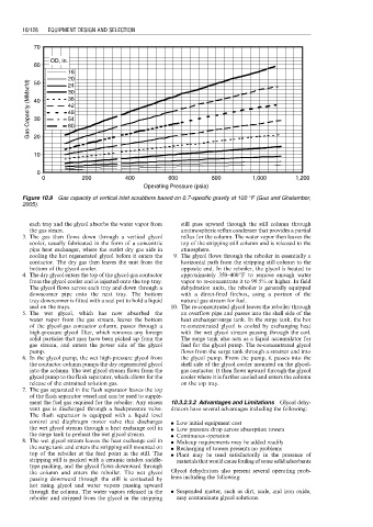
Figure 10.9 Gas capacity of vertical inlet scrubbers based on 0.7-specific gravity at 100 8F (Guo and Ghalambor,
2005).
each tray and the glycol absorbs the water vapor from still pass upward through the still column through
the gas steam. anatmospheric reflux condenser that provides a partial
3. The gas then flows down through a vertical glycol reflux for the column. The water vapor then leaves the
cooler, usually fabricated in the form of a concentric top of the stripping still column and is released to the
pipe heat exchanger, where the outlet dry gas aids in atmosphere.
cooling the hot regenerated glycol before it enters the 9. The glycol flows through the reboiler in essentially a
contactor. The dry gas then leaves the unit from the horizontal path from the stripping still column to the
bottom of the glycol cooler. opposite end. In the reboiler, the glycol is heated to
4. The dry glycol enters the top of the glycol-gas contactor approximately 350–4008F to remove enough water
from the glycol cooler and is injected onto the top tray. vapor to re-concentrate it to 99.5% or higher. In field
The glycol flows across each tray and down through a dehydration units, the reboiler is generally equipped
downcomer pipe onto the next tray. The bottom with a direct-fired firebox, using a portion of the
tray downcomer is fitted with a seal pot to hold a liquid natural gas stream for fuel.
seal on the trays. 10. The re-concentrated glycol leaves the reboiler through
5. The wet glycol, which has now absorbed the an overflow pipe and passes into the shell side of the
water vapor from the gas stream, leaves the bottom heat exchanger/surge tank. In the surge tank, the hot
of the glycol-gas contactor column, passes through a re-concentrated glycol is cooled by exchanging heat
high-pressure glycol filter, which removes any foreign with the wet glycol stream passing through the coil.
solid particles that may have been picked up from the The surge tank also acts as a liquid accumulator for
gas stream, and enters the power side of the glycol feed for the glycol pump. The re-concentrated glycol
pump. flows from the surge tank through a strainer and into
6. In the glycol pump, the wet high-pressure glycol from the glycol pump. From the pump, it passes into the
the contactor column pumps the dry regenerated glycol shell side of the glycol cooler mounted on the glycol-
into the column. The wet glycol stream flows from the gas contactor. It then flows upward through the glycol
glycol pump to the flash separator, which allows for the cooler where it is further cooled and enters the column
release of the entrained solution gas. on the top tray.
7. The gas separated in the flash separator leaves the top
of the flash separator vessel and can be used to supple-
ment the fuel gas required for the reboiler. Any excess 10.3.2.3.2 Advantages and Limitations Glycol dehy-
vent gas is discharged through a backpressure valve. drators have several advantages including the following:
The flash separator is equipped with a liquid level
control and diaphragm motor valve that discharges . Low initial equipment cost
the wet glycol stream through a heat exchange coil in . Low pressure drop across absorption towers
the surge tank to preheat the wet glycol stream. . Continuous operation
8. The wet glycol stream leaves the heat exchange coil in . Makeup requirements may be added readily
the surge tank and enters the stripping still mounted on . Recharging of towers presents no problems
top of the reboiler at the feed point in the still. The . Plant may be used satisfactorily in the presence of
stripping still is packed with a ceramic intalox saddle- materials that would cause fouling of some solid adsorbents
type packing, and the glycol flows downward through
the column and enters the reboiler. The wet glycol Glycol dehydrators also present several operating prob-
passing downward through the still is contacted by lems including the following:
hot rising glycol and water vapors passing upward
through the column. The water vapors released in the . Suspended matter, such as dirt, scale, and iron oxide,
reboiler and stripped from the glycol in the stripping may contaminate glycol solutions.