
Page 127 - Petroleum Production Engineering, A Computer-Assisted Approach
P. 127
Guo, Boyun / Computer Assited Petroleum Production Engg 0750682701_chap10 Final Proof page 122 4.1.2007 8:26pm Compositor Name: SJoearun
10/122 EQUIPMENT DESIGN AND SELECTION
10.2.4.2 Liquid Capacity Experience shows that for high-pressure separators used
Retention time of the liquid within the vessel determines for treating high gas/oil ratio well streams, the gas capacity
liquid capacity of a separator. Adequate separation re- is usually the controlling factor for separator selection.
quires sufficient time to obtain an equilibrium condition However, the reverse may be true for low-pressure sep-
between the liquid and gas phase at the temperature and arators used on well streams with low gas/oil ratios.
pressure of separation. The liquid capacity of a separator
relates to the retention time through the settling volume: Example Problem 10.1 Calculate the minimum required
size of a standard oil/gas separator for the following
1,440V L
q L ¼ (10:4) conditions. Consider both vertical and horizontal
t
separators.
where
Gas flow rate: 5.0 MMscfd
q L ¼ liquid capacity, bbl/day Gas-specific gravity: 0.7
V L ¼ liquid settling volume, bbl Condensate flow rate: 20 bbl/MMscf
t ¼ retention time, min Condensate gravity: 608API
Operating pressure: 800 psia
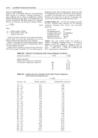
Table10.2presentstvaluesforvarioustypesofseparators Operating temperature: 808F
tested in fields. It is shown that temperature has a strong
impact on three-phase separations at low pressures. Solution The total required liquid flow capacity is
1
Tables 10.3 through 10.8 present liquid-settling volumes (5)(20) ¼ 100 bbl/day. Assuming a 20-in. 7 ⁄ 2 -ft vertical
with the conventional placement of liquid-level controls separator, Table 10.1 suggests an average K value of
for typical oil/gas separators. 0.205. The spreadsheet program Hall-Yarborogh-z.xls
3
Proper sizing of a separator requires the use of both Eq. gives z ¼ 0.8427 and r g ¼ 3:38 lb m =ft at 800 psig and
(10.3) for gas capacity and Eq. (10.4) for liquid capacity. 808F. Liquid density is calculated as
Table 10.2 Retention Time Required Under Various Separation Conditions
Separation condition T (8F) t (min)
Oil/gas separation 1
High-pressure oil/gas/water separation 2–5
Low-pressure oil/gas/water separation >100 5–10
90 10–15
80 15–20
70 20–25
60 25–30
Table 10.3 Settling Volumes of Standard Vertical High-Pressure Separators
(230–2,000 psi working pressure)
V L (bbl)
Size (D H) Oil/Gas separators Oil/Gas/Water separators
00 0
16 5 0.27 0.44
00 1 0
16 7 ⁄ 2 0.41 0.72
00 0
16 10 0.51 0.94
00 0
20 5 0.44 0.71
00 1 0
20 7 ⁄ 2 0.65 1.15
00 0
20 10 0.82 1.48
00 0
24 5 0.66 1.05
00 1 0
24 7 ⁄ 2 0.97 1.68
00 0
24 10 1.21 2.15
00 0
30 5 1.13 1.76
00 1 0
30 7 ⁄ 2 1.64 2.78
00 0
30 10 2.02 3.54
00 1 0
36 7 ⁄ 2 2.47 4.13
00 0
36 10 3.02 5.24
00 0
36 15 4.13 7.45
00 1 0
42 7 ⁄ 2 3.53 5.80
00 0
42 10 4.29 7.32
00 0
42 15 5.80 10.36
00 1 0
48 7 ⁄ 2 4.81 7.79
00 0
48 10 5.80 9.78
00 0
48 15 7.79 13.76
00 1
54 7 ⁄ 2 6.33 10.12
00 0
54 10 7.60 12.65
00 0
54 15 10.12 17.70
00 1 0
60 7 ⁄ 2 8.08 12.73
00 0
60 10 9.63 15.83
00 0
60 15 12.73 22.03
00 0
60 20 15.31 27.20