
Page 249 - Petroleum Production Engineering, A Computer-Assisted Approach
P. 249
Guo, Boyun / Computer Assited Petroleum Production Engg 0750682701_chap16 Final Proof page 247 21.12.2006 2:30pm
MATRIX ACIDIZING 16/247
Example Problem 16.2 A 60-ft thick, 50-md sandstone
pay zone at a depth of 9,500 ft is to be acidized with an
acid solution having a specific gravity of 1.07 and a
viscosity of 1.5 cp down a 2-in. inside diameter (ID) coil
tubing. The formation fracture gradient is 0.7 psi/ft. The
wellbore radius is 0.328 ft. Assuming a reservoir pressure
of 4,000 psia, drainage area radius of 1,000 ft, and a skin
factor of 15, calculate
(a) the maximum acid injection rate using safety margin
300 psi.
(b) the maximum expected surface injection pressure at
the maximum injection rate.
Solution
(a) The maximum acid injection rate:
4:917 10 6 kh p bd p Dp sf
q i, max ¼
m a ln 0:472r e þ S
r w
6
4:917 10 (50)(60) (0:7)(9,500) 4,000 300Þ
ð
¼
(1:5) ln 0:472(1,000) þ 15
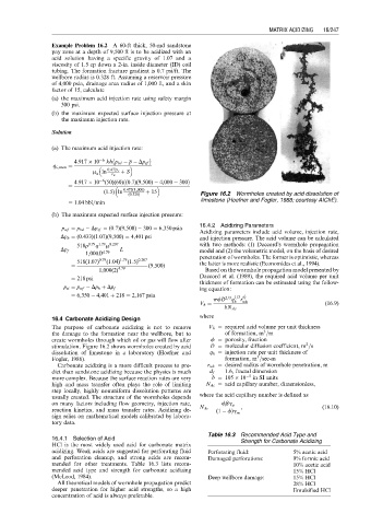
(0:328) Figure 16.2 Wormholes created by acid dissolution of
¼ 1:04 bbl=min limestone (Hoefner and Fogler, 1988; courtesy AIChE).
(b) The maximum expected surface injection pressure:
16.4.2 Acidizing Parameters
p wf ¼ p bd Dp sf ¼ (0:7)(9,500) 300 ¼ 6,350 psia
Acidizing parameters include acid volume, injection rate,
Dp h ¼ (0:433)(1:07)(9,500) ¼ 4,401 psi and injection pressure. The acid volume can be calculated
518r 0:79 1:79 m 0:207 with two methods: (1) Daccord’s wormhole propagation
q
Dp f ¼ L model and (2) the volumetric model, on the basis of desired
1,000D 4:79 penetration of wormholes. The former is optimistic, whereas
518(1:07) 0:79 (1:04) 1:79 (1:5) 0:207 the latter is more realistic (Economides et al., 1994).
¼ (9,500)
1,000(2) 4:79 Based on the wormhole propagation model presented by
¼ 218 psi Daccord et al. (1989), the required acid volume per unit
thickness of formation can be estimated using the follow-
p si ¼ p wf Dp h þ Dp f ing equation:
¼ 6,350 4,401 þ 218 ¼ 2,167 psia
r
pfD 2=3 1=3 d f
q
V h ¼ h wh (16:9)
bN Ac
where
16.4 Carbonate Acidizing Design
The purpose of carbonate acidizing is not to remove V h ¼ required acid volume per unit thickness
3
the damage to the formation near the wellbore, but to of formation, m =m
create wormholes through which oil or gas will flow after f ¼ porosity, fraction
2
stimulation. Figure 16.2 shows wormholes created by acid D ¼ molecular diffusion coefficient, m =s
dissolution of limestone in a laboratory (Hoefner and q h ¼ injection rate per unit thickness of
3
Fogler, 1988). formation, m =sec-m
Carbonate acidizing is a more difficult process to pre- r wh ¼ desired radius of wormhole penetration, m
dict than sandstone acidizing because the physics is much d f ¼ 1:6, fractal dimension
more complex. Because the surface reaction rates are very b ¼ 105 10 5 in SI units
high and mass transfer often plays the role of limiting N Ac ¼ acid capillary number, dimensionless,
step locally, highly nonuniform dissolution patterns are
usually created. The structure of the wormholes depends where the acid capillary number is defined as
on many factors including flow geometry, injection rate, fbg a
reaction kinetics, and mass transfer rates. Acidizing de- N Ac ¼ (1 f)g m , (16:10)
sign relies on mathematical models calibrated by labora-
tory data.
Table 16.3 Recommended Acid Type and
16.4.1 Selection of Acid Strength for Carbonate Acidizing
HCl is the most widely used acid for carbonate matrix
acidizing. Weak acids are suggested for perforating fluid Perforating fluid: 5% acetic acid
and perforation cleanup, and strong acids are recom- Damaged perforations: 9% formic acid
mended for other treatments. Table 16.3 lists recom- 10% acetic acid
mended acid type and strength for carbonate acidizing 15% HCl
(McLeod, 1984). Deep wellbore damage: 15% HCl
All theoretical models of wormhole propagation predict 28% HCl
deeper penetration for higher acid strengths, so a high Emulsified HCl
concentration of acid is always preferable.