
Page 253 - Petroleum Production Engineering, A Computer-Assisted Approach
P. 253
Guo, Boyun / Computer Assited Petroleum Production Engg 0750682701_chap17 Final Proof page 252 3.1.2007 9:19pm Compositor Name: SJoearun
17/252 PRODUCTION ENHANCEMENT
17.1 Introduction reduce the injection rate requirement, a low leaf-off frac-
turing fluid is essential. Also, to prop the fracture, the sand/
Hydraulic fracturing is a well-stimulation technique that is
most suitable to wells in low- and moderate-permeability proppant should have a compressive strength that is high
reservoirs that do not provide commercial production enough to resist the stress from the formation.
rates even though formation damages are removed by This chapter concisely describes hydraulic fracturing
acidizing treatments. treatments. For detailed information on this subject, see
Hydraulic fracturing jobs are carried out at well sites Economides and Nolte (2000). This chapter focuses on the
using heavy equipment including truck-mounted pumps, following topics:
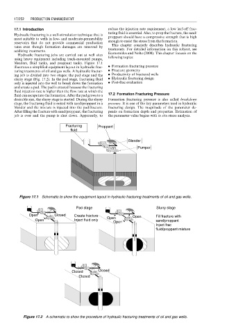
blenders, fluid tanks, and proppant tanks. Figure 17.1
illustrates a simplified equipment layout in hydraulic frac- . Formation fracturing pressure
turing treatments of oil and gas wells. A hydraulic fractur- . Fracture geometry
ing job is divided into two stages: the pad stage and the . Productivity of fractured wells
slurry stage (Fig. 17.2). In the pad stage, fracturing fluid . Hydraulic fracturing design
only is injected into the well to break down the formation . Post-frac evaluation
and create a pad. The pad is created because the fracturing
fluid injection rate is higher than the flow rate at which the
fluid can escape into the formation. After the pad grows to a 17.2 Formation Fracturing Pressure
desirable size, the slurry stage is started. During the slurry Formation fracturing pressure is also called breakdown
stage, the fracturing fluid is mixed with sand/proppant in a pressure. It is one of the key parameters used in hydraulic
blender and the mixture is injected into the pad/fracture. fracturing design. The magnitude of the parameter de-
After filling the fracture with sand/proppant, the fracturing pends on formation depth and properties. Estimation of
job is over and the pump is shut down. Apparently, to the parameter value begins with in situ stress analysis.
Fracturing Proppant
fluid
Blender
Pumper
Figure 17.1 Schematic to show the equipment layout in hydraulic fracturing treatments of oil and gas wells.
Pad stage Slurry stage
Open Closed Create fracture Open Fill fracture with
Open Inject fluid only Open sand/proppant
Open
Inject frac
fluid/proppant mixture
Closed Closed
Closed
Figure 17.2 A schematic to show the procedure of hydraulic fracturing treatments of oil and gas wells.