
Page 255 - Petroleum Production Engineering, A Computer-Assisted Approach
P. 255
Guo, Boyun / Computer Assited Petroleum Production Engg 0750682701_chap17 Final Proof page 254 3.1.2007 9:19pm Compositor Name: SJoearun
17/254 PRODUCTION ENHANCEMENT
1
ð
Solution mq i 1 nÞR 4
w w ¼ 2:56 , (17:6)
Overburden stress: E
rH (165)(10,000) where
s v ¼ ¼ ¼ 11,500 psi w w ¼ fracture width at wellbore, in.
144 144
m ¼ fluid viscosity, cp
Pore pressure:
q i ¼ pumping rate, bpm
p p ¼ (0:38)(10,000) ¼ 3,800 psi R ¼ the radius of the fracture, ft
E ¼ Young’s modulus, psi.
The effective vertical stress:
0
s ¼ s v ap p ¼ 11,500 (0:72)(3,800) ¼ 8,800 psi Assuming the fracture width drops linearly in the radial
v
direction, the average fracture width may be expressed as
The effective horizontal stress: mq i 1 nÞR 1 4
ð
0
0
s ¼ n s ¼ 0:25 ð 8,800Þ ¼ 2,900 psi w ¼ 0:85 E : (17:7)
h
1 n v 1 0:25
The minimum horizontal stress:
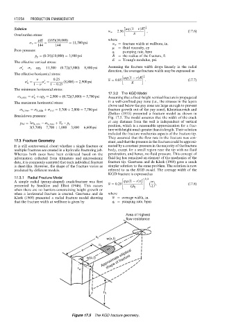
17.3.2 The KGD Model
0
s h, min ¼ s þ ap p ¼ 2,900 þ (0:72)(3,800) ¼ 5,700 psi Assuming that a fixed-height vertical fracture is propagated
h
The maximum horizontal stress: in a well-confined pay zone (i.e., the stresses in the layers
above and below the pay zone are large enough to prevent
s h, max ¼ s h, min þ s tect ¼ 5,700 þ 2,000 ¼ 7,700 psi fracture growth out of the pay zone), Khristianovich and
Zheltov (1955) presented a fracture model as shown in
Breakdown pressure:
Fig. 17.5. The model assumes that the width of the crack
at any distance from the well is independent of vertical
p bd ¼ 3s h, min s h, max þ T 0 p p position, which is a reasonable approximation for a frac-
¼ 3(5,700) 7,700 þ 1,000 3,800 ¼ 6,600 psi
ture with height much greater than its length. Their solution
included the fracture mechanics aspects of the fracture tip.
They assumed that the flow rate in the fracture was con-
17.3 Fracture Geometry stant, and that the pressure in the fracture could be approxi-
It is still controversial about whether a single fracture or mated by a constant pressure in the majority of the fracture
multiple fractures are created in a hydraulic fracturing job. body, except for a small region near the tip with no fluid
Whereas both cases have been evidenced based on the penetration, and hence, no fluid pressure. This concept of
information collected from tiltmeters and microseismic fluid lag has remained an element of the mechanics of the
data, it is commonly accepted that each individual fracture fracture tip. Geertsma and de Klerk (1969) gave a much
is sheet-like. However, the shape of the fracture varies as simpler solution to the same problem. The solution is now
predicted by different models. referred to as the KGD model. The average width of the
KGD fracture is expressed as
17.3.1 Radial Fracture Model " # 1=4
ð
p
A simple radial (penny-shaped) crack/fracture was first q i m 1 nÞx 2 f
w ¼ 0:29 , (17:8)
presented by Sneddon and Elliot (1946). This occurs 4
Gh f
when there are no barriers constraining height growth or
when a horizontal fracture is created. Geertsma and de where
Klerk (1969) presented a radial fracture model showing w ¼ average width, in.
that the fracture width at wellbore is given by q i ¼ pumping rate, bpm
Area of highest
flow resistance
x f w(x,t)
u x
x
shape of fracture
w(o,t) Approximate elliptical
r w
h f
Figure 17.5 The KGD fracture geometry.