
Page 259 - Petroleum Production Engineering, A Computer-Assisted Approach
P. 259
Guo, Boyun / Computer Assited Petroleum Production Engg 0750682701_chap17 Final Proof page 258 3.1.2007 9:19pm Compositor Name: SJoearun
17/258 PRODUCTION ENHANCEMENT
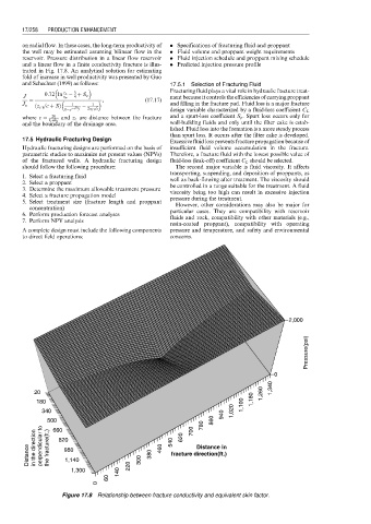
on radial flow. In these cases, the long-term productivity of . Specifications of fracturing fluid and proppant
the well may be estimated assuming bilinear flow in the . Fluid volume and proppant weight requirements
reservoir. Pressure distribution in a linear flow reservoir . Fluid injection schedule and proppant mixing schedule
and a linear flow in a finite conductivity fracture is illus- . Predicted injection pressure profile
trated in Fig. 17.8. An analytical solution for estimating
fold of increase in well productivity was presented by Guo
and Schechter (1999) as follows: 17.5.1 Selection of Fracturing Fluid
Fracturing fluid plays a vital role in hydraulic fracture treat-
3
J 0:72 ln r e r w þ S o ment because it controls the efficiencies of carrying proppant
4
¼ p ffiffiffi , (17:17)
J o ð z e c þ SÞ 1 ffiffi 1 ffiffi and filling in the fracture pad. Fluid loss is a major fracture
p
p
1 e cx f 2x f c design variable characterized by a fluid-loss coefficient C L
where c ¼ 2k and z e are distance between the fracture and a spurt-loss coefficient S p . Spurt loss occurs only for
z e wk f
and the boundary of the drainage area. wall-building fluids and only until the filter cake is estab-
lished. Fluid loss into the formation is a more steady process
than spurt loss. It occurs after the filter cake is developed.
17.5 Hydraulic Fracturing Design Excessive fluid loss prevents fracture propagation because of
Hydraulic fracturing designs are performed on the basis of insufficient fluid volume accumulation in the fracture.
parametric studies to maximize net present values (NPVs) Therefore, a fracture fluid with the lowest possible value of
of the fractured wells. A hydraulic fracturing design fluid-loss (leak-off) coefficient C L should be selected.
should follow the following procedure: The second major variable is fluid viscosity. It affects
transporting, suspending, and deposition of proppants, as
1. Select a fracturing fluid well as back-flowing after treatment. The viscosity should
2. Select a proppant be controlled in a range suitable for the treatment. A fluid
3. Determine the maximum allowable treatment pressure
4. Select a fracture propagation model viscosity being too high can result in excessive injection
5. Select treatment size (fracture length and proppant pressure during the treatment.
concentration) However, other considerations may also be major for
6. Perform production forecast analyses particular cases. They are compatibility with reservoir
7. Perform NPV analysis fluids and rock, compatibility with other materials (e.g.,
resin-coated proppant), compatibility with operating
A complete design must include the following components pressure and temperature, and safety and environmental
to direct field operations: concerns.
2,000
Pressure(psi)
0
20 1,260 1,340
180 1,100 1,180
340 940 1,020
500 620 700 780 860
660
540
Distance in the direction perpendicular to the fracture(ft.) 820 1,140 300 380 460 fracture direction(ft.)
Distance in
980
1,300 140 220
60
0
Figure 17.8 Relationship between fracture conductivity and equivalent skin factor.