Page 262 - Petroleum Production Engineering, A Computer-Assisted Approach
P. 262

Guo, Boyun / Computer Assited Petroleum Production Engg 0750682701_chap17 Final Proof page 261  3.1.2007 9:19pm Compositor Name: SJoearun


                                                                                 HYDRAULIC FRACTURING  17/261
                            Fracture height:     100 ft          Pad volume:
                            Fluid injection rate:  40 bpm                1   h  1   0:3875
                            Final proppant concentration: 3 ppg       « ¼    ¼        ¼ 0:44
                                                                         1 þ h  1 þ 0:3875
                                                                                                   4
                       Assuming KGD fracture, estimate              V pad ¼ V inj « ¼ (6:26   10 )0:44ð  Þ ¼ 2:76   10 gal
                                                                                     4
                       a. Fluid volume requirement
                                                                 It will take 17 min to pump the pad volume at an injection
                       b. Proppant mixing schedule               rate of 40 bpm.
                       c. Proppant weight requirement            b. Proppant mixing schedule:
                       d. Propped fracture width
                                                                                     t   17    0:44
                                                                             c p (t) ¼ (3)
                       Solution                                                      37   17
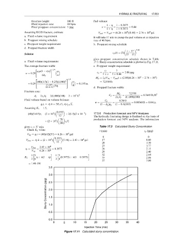
                                                                 gives proppant concentration schedule shown in Table
                       a. Fluid volume requirements:             17.3. Slurry concentration schedule is plotted in Fig. 17.11.
                       The average fracture width:               c. Proppant weight requirement:
                              "        # 1=4
                               q i m(1   n)x 2                          c f    3
                                           p
                          w w ¼ 0:29   f                           c   c p ¼  1 þ «  ¼  1 þ 0:44  ¼ 2:08 ppg
                                  Gh f     4
                                                                                             4
                                                                                                      4
                                                                       c
                              2                  3 1=4            M p ¼   c p (V inj   V pad ) ¼ (2:08)(6:26   10   2:76   10 )
                          ¼ 0:29 4 (40)(1:5)(1   0:25)(1,000) 2 5     ¼ 0:195 in:  ¼ 72,910 lb
                                     (3 10 6 )  (70)  4
                                    2(1þ0:25)                    d. Propped fracture width:
                       Fracture area:
                                                                               M p    72,910           3
                                                      5
                             A f ¼ 2x f h f ¼ 2(1,000)(100) ¼ 2   10 ft 2  C p ¼   ¼          ¼ 0:3645 lb=ft
                                                                              2x f h f  2(1,000)(100)
                       Fluid volume based on volume balance:                     0:3645
                                                  p ffiffiffi           w ¼   C p  ¼          ¼ 0:00368 ft ¼ 0:04 in:
                                       w
                                 q i t i ¼ A f   w þ 2K L C L A f r p t i :  (1   f p )r p  (1   0:4)(165)
                       Assuming K L ¼ 1:5,

                                           0:195
                                         5
                                                           3
                         (40)(5:615)t i ¼ (2   10 )  12  þ 2(1:5)(2   10 )  17.5.6 Production forecast and NPV Analyses

                                              70 p ffiffiffi           The hydraulic fracturing design is finalized on the basis of
                                                                 production forecast and NPV analyses. The information
                                          5
                                      (2   10 )  t i
                                            100
                       gives t i ¼ 37 min.                           Table 17.3 Calculated Slurry Concentration
                         Check K L value:
                                                                     t (min)                    c p (ppg)
                                                  4
                         V inj ¼ q i t ¼ (40)(42)(37) ¼ 6:26   10 gal
                                                                       0                          0
                                          0:195
                                                           4
                                       5
                               w
                        V frac ¼ A f   w ¼ (2   10 )  (7:48) ¼ 2:43   10 gal  17                 0.00
                                           12
                                                                      20                         1.30
                           V frac  2:43   10 4                        23                         1.77
                        h ¼    ¼        ¼ 0:3875                      26                         2.11
                            V inj  6:26   10 4                        29                         2.40

                           1 3            1 3                         32                         2.64
                       K L ¼  h þ p(1   h) ¼  (0:3875) þ p(1   0:3875)  35                       2.86
                           2 8            2 8
                                                                      37                         3.00
                          ¼ 1:48 OK
                                      3.5
                                      3.0
                                     Slurry Concentration (ppg)  2.0
                                      2.5
                                      1.5
                                      1.0
                                      0.5
                                      0.0
                                         0     5     10    15     20    25    30     35    40
                                                            Injection Time (min)
                                               Figure 17.11 Calculated slurry concentration.
   257   258   259   260   261   262   263   264   265   266   267