
Page 265 - Petroleum Production Engineering, A Computer-Assisted Approach
P. 265
Guo, Boyun / Computer Assited Petroleum Production Engg 0750682701_chap17 Final Proof page 264 3.1.2007 9:19pm Compositor Name: SJoearun
17/264 PRODUCTION ENHANCEMENT
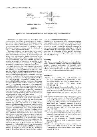
Bilinear flow:
Fracture
linear flow:
Pseudo-radial flow
Reservoir linear flow
Figure 17.13 Four flow regimes that can occur in hydraulically fractured reservoirs.
The bilinear flow regime means two linear flows occur 17.6.3 Other evaluation techniques
simultaneously. One flow is a linear flow within the frac- In addition to the pressure-matching and pressure buildup
ture and the other is a linear flow in the formation toward data analyses, other techniques can be used to verify the
the fracture. Bilinear flow analysis gives an estimate of fracture profile created during a fracpack operation. These
fracture length and conductivity. A calculated pressure techniques include (1) pumping radioactive materials in
distribution during a bilinear flow is illustrated in the proppant stages and running tracer logs to verify the
Fig. 17.2 (Guo and Schechter, 1999). fracture heights, (2) running production logging tools to
The formation linear flow toward the fracture occurs determine the production profiles, and (3) conducting
after the bilinear flow. Linear flow analysis yields an esti- back-pressure and performing Nodal analysis to verify
mate of formation permeability in the direction perpen- the well deliverability.
dicular to the fracture face. If the test time is long enough
and there is no boundary effect, a system pseudo-radial
flow will eventually occur. Pseudo-radial flow analysis Summary
provides an estimate of formation permeability in the
This chapter presents a brief description of hydraulic frac-
radial direction. The reader is referred to Chapter 15 for turing treatments covering formation fracturing pressure,
analysis and interpretation of pressure transient data. fracture geometry, productivity of fractured wells,
It is important to note that by nomeansdoes the pressure- hydraulic fracturing design, and post-frac evaluation.
match procedure and the pressure transient data analysis More in-depth discussions can be found from Economides
give details of the fracture geometry such as fracture width et al. (1994) and Economides and Nolte (2000).
near the wellbore, which frequently dominates the post-
treatment well performance. The fracture width near the
wellbore can be significantly lower than that in the region
away from the wellbore.This can occur becauseof a number References
of mishaps. Overdisplacement of proppant leads to the frac- argawal, r.g., carter, r.d., and pollock, c.b.
ture unsupported near the wellbore, resulting in fracture Evaluation and prediction of performance of low-
closure. Fluid backflow reduces the amount of proppant permeability gas wells stimulated by massive hydraulic
near the wellbore, which results in less fracture width sup- fracturing. JPT March 1979, Trans. AIME
ported. If the proppant grains do not have compressive 1979;267:362–372.
strength to withstand the stress concentration in the near-
wellboreregion,theywillbecrushedduringfractureclosure, barree, r.d. A practical numerical simulator for three
resulting in tight fracture near the wellbore. The reduced dimensional fracture propagation in heterogeneous
fracture width near the wellbore affects well productivity media. Proceedings of the Reservoir Simulation Sym-
because of the fracture choking effect. Post-treatment flow posium, San Francisco, CA, 403-411 Nov. 1983. SPE
tests should be run to verify well performance. 12273.
The effect of near-wellbore fracture geometry on post- burton, r.c., davis, e.r., hodge, r.m., stomp, r.j., palthe,
treatment well production is of special significance in p.w., and saldungaray, p. Innovative completion
deviated and horizontal wells (Chen and Economides,
design and well performance evaluation for effective
1999). This is because a fracture from an arbitrarily
Frac-packing of long intervals: a case study from the
oriented well ‘‘cuts’’ the wellbore at an angle, thereby
West Natuna Sea, Indonesia. Presented at the SPE
limiting the communication between the wellbore and the
International Petroleum Conference and Exhibition
reservoir. This feature of fluid entry to the wellbore itself
causes the fracture-choking effect, even though the near- held 10–12 February 2002, in Villahermosa, Mexico.
wellbore fracture is perfectly propped. Certainly, a hori- Paper SPE 74351.
zontal well in the longitudinal to the fracture direction and chen, z. and economides, m.j. Effect of near-wellbore
using 180-degree perforation phasing that can be oriented fracture geometry on fracture execution and post-treat-
will eliminate the problem. However, to align the horizon- ment well production of deviated and horizontal wells.
tal wellbore in the longitudinal to the fracture direction, SPE Prod. Facilities August 1999.
the horizontal wellbore has to be drilled in the direction cinco-ley, h. and samaniego, f. Transient pressure
parallel to the maximum horizontal stress direction. The
orientation of the stress can be obtained by running tests in analysis for fractured wells. J. Petroleum Technol.
a vertical pilot hole of the horizontal well. Special log September 1981.
imaging (e.g., FMI and FMS) can be run in combination cleary, m.p. Comprehensive design formulae for
with an injection test at small-rate MDT or large-scale hydraulic fracturing. Presented at the SPE Annual
minifrac to fracture the formation and read directly the Technology Conference held in Dallas, Texas, Septem-
image in the wellbore after the fracture has been created. ber 1980. SPE 9259.