
Page 260 - Petroleum Production Engineering, A Computer-Assisted Approach
P. 260
Guo, Boyun / Computer Assited Petroleum Production Engg 0750682701_chap17 Final Proof page 259 3.1.2007 9:19pm Compositor Name: SJoearun
HYDRAULIC FRACTURING 17/259
17.5.2 Selection of Proppant s ¼ n rH
0
Proppant must be selected on the basis of in situ stress h 1 n 144 ap p
conditions. Major concerns are compressive strength and 0:25 (165)(10,000)
the effect of stress on proppant permeability. For a vertical ¼ (0:7)(2500) ¼ 3,236 psi
fracture, the compressive strength of the proppant should 1 0:25 144
be greater than the effective horizontal stress. In general, Therefore, the minimum required proppant compressive
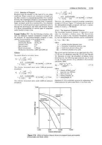
bigger proppant yields better permeability, but proppant strength is 3,236 psi. Figure 17.9 indicates that the pack of
size must be checked against proppant admittance criteria the intermediate-strength proppants will have a perme-
through the perforations and inside the fracture. Figure ability of about k f ¼ 500 darcies.
17.9 shows permeabilities of various types of proppants
under fracture closure stress. 17.5.3 The maximum Treatment Pressure
The maximum treatment pressure is expected to occur
Example Problem 17.3 For the following situation, esti- when the formation is broken down. The bottom-hole
mate the minimum required compressive strength of 20/ pressure is equal to the formation breakdown pressure
40 proppant. If intermediate-strength proppant is used, p bd and the expected surface pressure can be calculated by
estimate the permeability of the proppant pack: p si ¼ p bd Dp h þ Dp f , (17:18)
Formation depth: 10,000 ft
Overburden density: 165 lb m =ft 3 where
Poison’s ratio: 0.25 p si ¼ surface injection pressure, psia
Biot constant: 0.7 p bd ¼ formation breakdown pressure, psia
Reservoir pressure: 6,500 psi Dp h ¼ hydrostatic pressure drop, psia
Production drawdown: 2,000 and 4,000 psi Dp f ¼ frictional pressure drop, psia.
Solution The second and the third term in the right-hand side of Eq.
(17.18) can be calculated using Eq. (11.93) (see Chapter
The initial effective horizontal stress:
11). However, to avert the procedure of friction factor
n rH determination, the following approximation may be used
0
s ¼ ap p
h
1 n 144 for the frictional pressure drop calculation (Economides
and Nolte, 2000):
0:25 (165)(10,000)
¼ (0:7)(6500) ¼ 2,303 psi 518r 0:79 1:79 m 0:207
q
1 0:25 144 Dp f ¼ L, (17:19)
1,000D 4:79
The effective horizontal stress under 2,000-psi pressure
drawdown: where
r ¼ density of fluid, g=cm 3
n rH
0
s ¼ 1 n 144 ap p q ¼ injection rate, bbl/min
h
m ¼ fluid viscosity, cp
0:25 (165)(10,000) D ¼ tubing diameter, in.
¼ (0:7)(4500) ¼ 2,770 psi L ¼ tubing length, ft.
1 0:25 144
The effective horizontal stress under 4,000-psi pressure Equation (17.19) is relatively accurate for estimating fric-
drawdown: tional pressures for newtonian fluids at low flow rates.
Figure 17.9 Effect of fracture closure stress on proppant pack permeability
(Economides and Nolte, 2000).