
Page 141 - Materials Chemistry, Second Edition
P. 141
124 Practical Design Calculations for Groundwater and Soil Remediation
the effluent value at the exit condition. Under the steady-state conditions, the
effluent concentration and concentration at any location within the reactor
should not change with time.
It should be noted that CFSTRs and PFRs are ideal reactors. The continu-
ous-flow reactors in the real world behave somewhere between these ideal
cases. The ideal CFSTRs are more resistant to shock loadings because the
influent would be mixed with the reactor content immediately. They are a
better choice if the process is sensitive to shock loadings (e.g., biological pro-
cesses). On the other hand, the ideal PFRs provide the same residence time
for all the influent flow. They are a better choice for chlorine contact tanks
in which a minimum contact time between pathogens and disinfectants is
needed. (Note: the residence times of influent parcels in an ideal CFSTR can
range from extremely short to extremely long.)
4.4.1 Batch Reactors
Let us consider a batch reactor with a first-order reaction. By combining Equations
(4.10) and (4.11), the mass-balance equation can be expressed as follows:
dC
V = ( V × γ= V(− kC)
)
dt
or (4.15)
dC =− kC
dt
It is a first-order differential equation and can be integrated with the initial
condition (C = C at t = 0) and the final condition (C = C at t = residence time
i
f
(τ)). The residence time can be defined as the time that the fluid stays inside
the reactor and undergoes reaction. The integral of Equation (4.15) is
C f −τ −τ
= e or C f = () (4.16)
k
k
Ce
i
C i
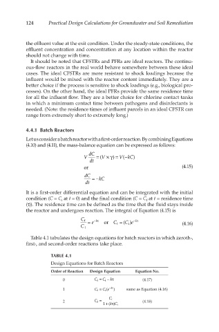
Table 4.1 tabulates the design equations for batch reactors in which zeroth-,
first-, and second-order reactions take place.
TABLE 4.1
Design Equations for Batch Reactors
Order of Reaction Design Equation Equation No.
0 C f = C i − kτ (4.17)
1 C f = C e( i −τ ) same as Equation (4.16)
k
2 C f = C i (4.18)
+τ
1( kC) i