
Page 120 -
P. 120
MIXING, COAGULATION, AND FLOCCULATION 6.11
PRESSURE GAUGE
/
, /,,FLOW CONTROL
CHEMICAL FEED
,'-'-r~ i/ / VALVE [
mV
INLET
CHANNEL
) ,i
PLANT INLET /
PIPE ZONE OF MIXING
!
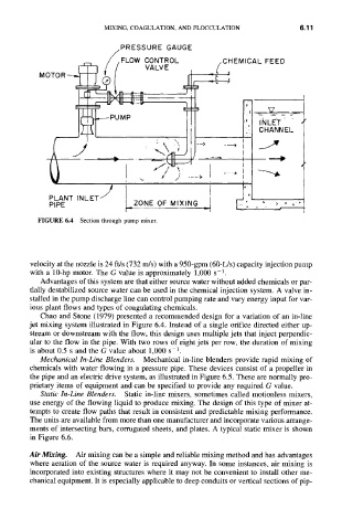
FIGURE 6.4 Section through pump mixer.
velocity at the nozzle is 24 ft/s (732 m/s) with a 950-gpm (60-L/s) capacity injection pump
with a 10-hp motor. The G value is approximately 1,000 s -1.
Advantages of this system are that either source water without added chemicals or par-
tially destabilized source water can be used in the chemical injection system. A valve in-
stalled in the pump discharge line can control pumping rate and vary energy input for var-
ious plant flows and types of coagulating chemicals.
Chao and Stone (1979) presented a recommended design for a variation of an in-line
jet mixing system illustrated in Figure 6.4. Instead of a single orifice directed either up-
stream or downstream with the flow, this design uses multiple jets that inject perpendic-
ular to the flow in the pipe. With two rows of eight jets per row, the duration of mixing
is about 0.5 s and the G value about 1,000 s-1.
Mechanical In-Line Blenders. Mechanical in-line blenders provide rapid mixing of
chemicals with water flowing in a pressure pipe. These devices consist of a propeller in
the pipe and an electric drive system, as illustrated in Figure 6.5. These are normally pro-
prietary items of equipment and can be specified to provide any required G value.
Static In-Line Blenders. Static in-line mixers, sometimes called motionless mixers,
use energy of the flowing liquid to produce mixing. The design of this type of mixer at-
tempts to create flow paths that result in consistent and predictable mixing performance.
The units are available from more than one manufacturer and incorporate various arrange-
ments of intersecting bars, corrugated sheets, and plates. A typical static mixer is shown
in Figure 6.6.
Air Mixing. Air mixing can be a simple and reliable mixing method and has advantages
where aeration of the source water is required anyway. In some instances, air mixing is
incorporated into existing structures where it may not be convenient to install other me-
chanical equipment. It is especially applicable to deep conduits or vertical sections of pip-