
Page 121 -
P. 121
6.12 CHAPTER SIX
I ~ MOTOR
[
• '.l/
GEAR DRIVE -----...~p
~~..__._ SHAFT GLAND
==J ~ __--ALTERNATIVE
~J/~ / (DOWNSTREAM)CHEMICAL
]( I'-I / I-I FEED LINE
i-I---/~
I c
PROPELLERS
STATOR TYR
FIGURE 6.5 Typical in-line blender (mixer).
ing. Energy applied in adding air may be computed as the volume of water displaced
per unit time multiplied by the depth below the free surface, as shown in the following
equation:
Qh
hp = 528
where Q = free air discharge, ft3/min
h = depth of air inlet nozzle below water surface, ft
hp = horsepower input
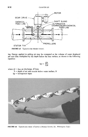
FIGURE 6.6 Typical static mixer. (Courtesy of Komax Systems, Inc., Wilmington, Calif.)