
Page 122 -
P. 122
MIXING, COAGULATION, AND FLOCCULATION 6.13
Energy applied by air injection may be varied directly by adjusting airflow. Air mix-
ing is not widely used, and before it is incorporated into a design, an inspection should
be made to determine whether scum and floatable material would be a problem. Limited
quantities of floating scum (or sludge) may be accepted onto filters, but certain coagu-
lants and algae may increase scums.
Hydraulic Mixing. Hydraulic mixing can be achieved by using V-notch weirs, Parshall
flumes, orifices, throttled valves, swirl chambers, and simple turbulence caused by ve-
locity in a pipe, fitting, or conduit. Hydraulic mixing is a nonbackmix method that can
sometimes be highly efficient. The principal problem is that energy input varies with the
flow. However, if a plant has relatively constant flows, energy variations may not be a
concern. Seasonal flow variations can sometimes be overcome by varying the number of
plant mixing modules in operation to maintain more or less constant flows on those mod-
ules in operation.
Total head loss across a throttled valve used for mixing coagulant chemicals should
not exceed 4 ft (3.2 m). If head loss exceeds this amount, coagulants should be added to
the flow downstream of the valve in the zone of decaying energy because excessive con-
fined energy may shear polymers.
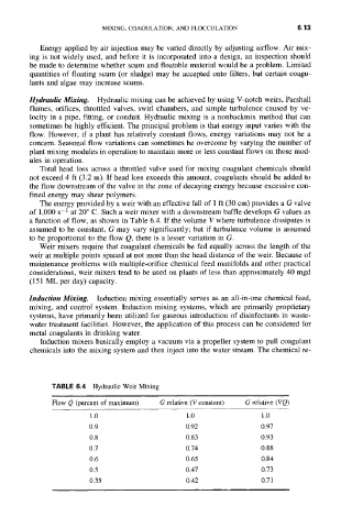
The energy provided by a weir with an effective fall of 1 ft (30 cm) provides a G valve
of 1,000 s-1 at 20 ° C. Such a weir mixer with a downstream baffle develops G values as
a function of flow, as shown in Table 6.4. If the volume V where turbulence dissipates is
assumed to be constant, G may vary significantly; but if turbulence volume is assumed
to be proportional to the flow Q, there is a lesser variation in G.
Weir mixers require that coagulant chemicals be fed equally across the length of the
weir at multiple points spaced at not more than the head distance of the weir. Because of
maintenance problems with multiple-orifice chemical feed manifolds and other practical
considerations, weir mixers tend to be used on plants of less than approximately 40 mgd
(151 ML per day) capacity.
Induction Mixing. Induction mixing essentially serves as an all-in-one chemical feed,
mixing, and control system. Induction mixing systems, which are primarily proprietary
systems, have primarily been utilized for gaseous introduction of disinfectants in waste-
water treatment facilities. However, the application of this process can be considered for
metal coagulants in drinking water.
Induction mixers basically employ a vacuum via a propeller system to pull coagulant
chemicals into the mixing system and then inject into the water stream. The chemical re-
TABLE 6.4 Hydraulic Weir Mixing
Flow Q (percent of maximum) G relative (V constant) G relative (VQ)
1.0 1.0 1.0
0.9 0.92 0.97
0.8 0.83 0.93
0.7 0.74 0.88
O.6 0.65 O.84
0.5 0.47 0.73
0.35 0.42 0.71