
Page 124 -
P. 124
MIXING, COAGULATION, AND FLOCCULATION 6,15
MIXED WATER CONDUIT
' " --- = ~ ' I ---,-- --. I . . . . CLARIFIE
;. j 1 i
- . - i i
I
CROSS SECTION HORIZONTAL SHAFT PADDLE
FLOCCULATORS 4- COMPARTMENT,
.,,..MOTOR AND GEAR DRIVE
: ~1 ~' i, ;; 1 L '= .'
~,l 1~:1 , ,-'-"/---'-,----~--'":, ---',----,-I--"f'-===--=,--~,-' [I
. ' ~ ' =' ~ : , ; ' I ' T'="H
LONGITUDINAL SECTION HORIZONTAL SHAFT PADDLE
FLOCCULATORS SUBMERGED RT. ANGLE GEAR DRIVE
,,...-MOTOR AND GEAR DRIVE
T'~ '" = 'z °."~
LONGITUDINAL SECTION
HORIZONTAL AXIAL FLOW PADDLE FLOCCULATORS
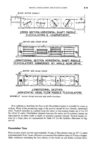
FIGURE 6.7 Sections through horizontal shaft paddle flocculator.
Flow splitting to distribute the flow to the flocculation basins is normally by weirs or
orifices. Weirs at the postmixing stage of the process should be low-velocity, submerged
weirs. Typical velocities in conduits from the mixer to flocculation basins are 1.5 to 3.0
ft/s (46 to 91 crrds). Distribution channels between the mixer and flocculation basins are
often tapered, in either width or depth, to maintain constant velocity. Typical design cri-
teria for a large plant are summarized in Table 6.5 for the facilities illustrated in Fig-
ure 6.8.
Flocculation Time
Most modem plants provide approximately 20 min of flocculation time (at 20 ° C) under
maximum plant flows. Some references recommend flocculation times of 30 min or longer.
Older references (including the first edition of this book) do not define nominal flows,