
Page 334 -
P. 334
11.14 CHAPTER ELEVEN
C: 300% controlled
100
- - ~ ~ ~ . . . ~ ~ ~ recycle
~ A
_ ~ No sludge------~ ~ : , "~ NN~ D: COntact clarifier
/
80
70
recycle control ~ ~
60
50
40
- B: 25% controlled-'f \ \ \ \
30
20
g. 10
0.2 .3 .4.5.6.7 1.0 1.52.0 3 4 5 6
10 15 20 30 4050 100 150
Nominal micrometer diameter log scale
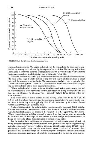
FIGURE 11.4 Particle size distribution comparison.
cium carbonate crystals. The depth and density of the residuals in the basin can be con-
trolled by wasting residuals and by the degree of recirculation. The mixing and recircu-
lation zone is separated from the sedimentation zone by a conical baffle wall within the
basin. An example of a solids contact unit is shown in Figure 11.5.
Effective solids contact units pull settled residuals from near the floor at the center of
the basin with a large-diameter turbine or impeller and recirculate the residuals at a high
rate with the water entering the basin. The maximum recirculation rate is typically 10 to
1 based on incoming flow. The mixer is provided with a variable-speed drive for adjust-
ing the recirculation rate to meet treatment conditions.
Where multiple solids contact units are installed, small recirculation pumps, operated
to recirculate solids from one unit to another, are often used during start-up of a unit that
has been out of service for cleaning. This is especially helpful during periods of low wa-
ter temperature.
Side water depth of solids contact basins usually varies from 14 to 18 ft (4.3 to
5.5 m) and depends on basin size and the equipment manufacturer's requirements. Con-
tact time in the mixing zone is typically 15 to 30 min, measured by the volume of water
within and directly under the baffle wall.
Surface loading rate in the sedimentation zone is generally measured 2 ft (0.6 m) be-
low the water surface, based on the surface area between the baffle wall and the basin
wall. Surface loading rates are usually in the range of 1.0 to 1.75 gpm/ft 2 (2.4 to 4.3 m/h).
Where coagulation for turbidity removal is required, surface loading rates are generally
in the lower end of this range or less. Where possible, design requirements should be
based on successful plants using the same or similar source water.
For the straight lime and lime-soda ash process, residuals are composed primarily of
heavy calcium carbonate crystals without the more gelatinous and lighter magnesium hy-
droxide component. The heavy calcium carbonate crystals create some difficulty in re-
circulating residuals. In any case, the manufacturer should be advised of the nature of the
process so that the basin design will function properly. Equipment specifications should
establish a minimum percentage of solids to be maintained in the mixing zone. A mini-