
Page 59 - 15 Dangerously Mad Projects for the Evil Genius
P. 59
Chapter 4 ■ Mini Laser Turret 39
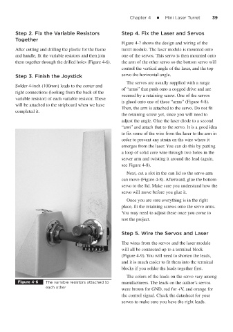
Step 2. Fix the Variable Resistors Step 4. Fix the Laser and Servos
Together
Figure 4-7 shows the design and wiring of the
After cutting and drilling the plastic for the frame turret module. The laser module is mounted onto
and handle, fit the variable resistors and then join one of the servos. This servo is then mounted onto
them together through the drilled holes (Figure 4-6). the arm of the other servo so the bottom servo will
control the vertical angle of the laser, and the top
Step 3. Finish the Joystick servo the horizontal angle.
The servos are usually supplied with a range
Solder 4-inch (100mm) leads to the center and
of “arms” that push onto a cogged drive and are
right connections (looking from the back of the
secured by a retaining screw. One of the servos
variable resistor) of each variable resistor. These
is glued onto one of these “arms” (Figure 4-8).
will be attached to the stripboard when we have
Then, the arm is attached to the servo. Do not fit
completed it.
the retaining screw yet, since you will need to
adjust the angle. Glue the laser diode to a second
“arm” and attach that to the servo. It is a good idea
to fix some of the wire from the laser to the arm in
order to prevent any strain on the wire where it
emerges from the laser. You can do this by putting
a loop of solid core wire through two holes in the
server arm and twisting it around the lead (again,
see Figure 4-8).
Next, cut a slot in the can lid so the servo arm
can move (Figure 4-8). Afterward, glue the bottom
servo to the lid. Make sure you understand how the
servo will move before you glue it.
Once you are sure everything is in the right
place, fit the retaining screws onto the servo arms.
You may need to adjust these once you come to
test the project.
Step 5. Wire the Servos and Laser
The wires from the servos and the laser module
will all be connected up to a terminal block
(Figure 4-9). You will need to shorten the leads,
and it is much easier to fit them into the terminal
blocks if you solder the leads together first.
The colors of the leads on the servo vary among
Figure 4-6 The variable resistors attached to manufacturers. The leads on the author’s servos
each other
were brown for GND, red for +V, and orange for
the control signal. Check the datasheet for your
servos to make sure you have the right leads.