
Page 62 - 15 Dangerously Mad Projects for the Evil Genius
P. 62
42 15 Dangerously Mad Projects for the Evil Genius
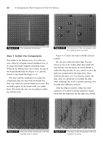
Figure 4-12 The prepared stripboard Figure 4-14 The bottom of the stripboard with
the linking wires in place
Step 7. Solder the Components Figure 4-15 shows the board with the resistors
in place.
First solder in the linking wires. Use solid core
We can now solder the timer chip. You may
wire, either by stripping normal insulated wire, or
choose to use an IC socket rather than solder the
by using previously snipped component leads.
chip directly onto the board. If you do decide to
When all the linking wires are in place, the top of
solder the chip directly, be very careful to put it the
the board should look like Figure 4-13, and the
right way around and in the right place. Once
bottom of the board like Figure 4-14.
soldered into place, it is very hard to remove the
The trick with the stripboard is to solder the
chip. Also, be careful not to overheat the chip
components that rise least from the board first.
while soldering. Try to do it quickly, pausing a few
That way, when you put the board on its back, they
seconds after soldering each pin.
are held in place by the board while you solder
After the chip (or socket), solder the small
them. This being the case, we are going to solder
capacitors (C2 and C4) and the transistor. Again,
the resistors next.
check that the transistors are the right way around.
Figure 4-13 The top of the stripboard with the Figure 4-15 The top of the stripboard with the
linking wires in place resistors in place