
Page 61 - 15 Dangerously Mad Projects for the Evil Genius
P. 61
Chapter 4 ■ Mini Laser Turret 41
Using Figure 4-7 as a reference, wire up the the servos and the 100 resistor. The resistor leads
turret. should be shortened and the positive lead of the
All the negative leads from both servos and the laser module connected to the end of the resistor.
laser module go into the left-hand terminal block. The final two connections for the terminal block
The next terminal block has the positive leads of are the control signals from the servos.
Figure 4-10 shows the completed laser turret
module, with the ribbon cable attached and ready
to be connected to the stripboard.
Step 6. Prepare the Stripboard
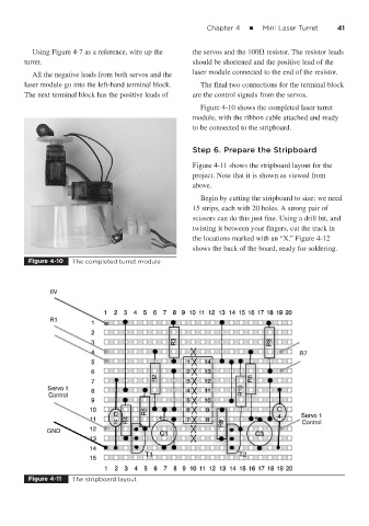
Figure 4-11 shows the stripboard layout for the
project. Note that it is shown as viewed from
above.
Begin by cutting the stripboard to size: we need
15 strips, each with 20 holes. A strong pair of
scissors can do this just fine. Using a drill bit, and
twisting it between your fingers, cut the track in
the locations marked with an “X.” Figure 4-12
shows the back of the board, ready for soldering.
Figure 4-10 The completed turret module
Figure 4-11 The stripboard layout