Page 63 - 15 Dangerously Mad Projects for the Evil Genius
P. 63

Chapter 4    ■   Mini Laser Turret     43


        Finally, we can solder the large capacitors (C1 and  Step 8. Wire Everything Together
        C3) into place, making sure the polarity is correct.
                                                           Having built the turret module joystick and
        The negative lead is the shorter of the two leads
                                                           stripboard, it is now time to wire everything
        and often has a diamond next to it.
                                                           together. Figure 4-18 shows the wiring diagram
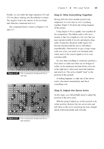
           The completed board is shown in Figures 4-16
                                                           of the project.
        and 4-17.
                                                             Using Figure 4-18 as a guide, wire together all
                                                           the components. The ribbon cable to the servo
                                                           module is fine for a length of a few feet, but you
                                                           may run into trouble if you try and attach a long
                                                           cable. Eventually, the pulse width signal will
                                                           become distorted and the servos will behave
                                                           unpredictably. Alternatively, to get a longer range
                                                           with your wires, use multi-core shielded cable,
                                                           where each of the control signals is in its own
                                                           screened cable.

                                                             So, now that everything is connected, perform a
                                                           final check to make sure there are no bridges of
                                                           solder on the stripboard and that all the wires are
                                                           in the right place. Afterward, insert the batteries
                                                           and turn it on. The servos should “snap” to the
         Figure 4-16   The completed stripboard from
                                                           position of the joystick.
                       the top
                                                             If nothing happens, or only one of the servos
                                                           works, disconnect immediately and check
                                                           everything over.


                                                           Step 9. Adjust the Servo Arms

                                                           At this stage, you will probably need to adjust the
                                                           position of the servo arms.
                                                             With the project turned on, set the joystick to its
                                                           center position. Remove the two server arms and
                                                           refit them so the servo is pointing the laser straight
                                                           ahead, both horizontally and vertically.


         Figure 4-17   The completed stripboard from
                       the bottom
   58   59   60   61   62   63   64   65   66   67   68