
Page 105 - 3D Fibre Reinforced Polymer Composites
P. 105
94 30 Fibre Reinforced Polymer Composites
As shown in Figure 4.15, there exists a remarkable difference between the idealised and
true geometry in a 3D orthogonal woven composite material. The procedure to
determine all idealised geometrical dimensions was detailed in Tan et a1 (2000b).
Figure 4.15 schematically shows the scheme used to determine the cross-sectional
dimensions of a rectangular shaped stuffer yarn.
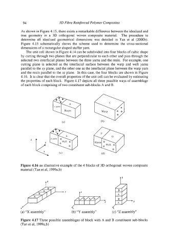
The unit cell shown in Figure 4.14 can be subdivided into four blocks of cubic shape
by cutting through two planes that are perpendicular to each other and pass through the
selected two interfacial planes between the three yarns and the resin. For example, one
cutting plane is selected as the interfacial surface between the warp and weft yams
parallel to the xy plane, and the other one as the interfacial plane between the warp yarn
and the resin parallel to the xz plane. In this case, the four blocks are shown in Figure
4.16. It is clear that the overall properties of the unit cell can be evaluated by estimating
the properties of each block. Figure 4.17 depicts all three possible ways of assemblage
of each block comprising of two constituent sub-blocks A and B.
Figure 4.16 an illustrative example of the 4 blocks of 3D orthogonal woven composite
material (Tan et al, 1999a,b)
J$
tz -
X
Y
4
X
(a) “X assembly” (b) “Y assembly” (c) ‘Z assembly”
Figure 4.17 Three possible assemblages of block with A and B constituent sub-blocks
(Tan et al, 1999a,b)