
Page 27 - 3D Fibre Reinforced Polymer Composites
P. 27
16 30 Fibre Reinforced Polymer Composites
the creel or through hanging small weights on the yarns before entering the lifting
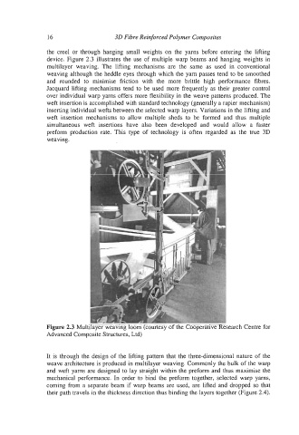
device. Figure 2.3 illustrates the use of multiple warp beams and hanging weights in
multilayer weaving. The lifting mechanisms are the same as used in conventional
weaving although the heddle eyes through which the yarn passes tend to be smoothed
and rounded to minimise friction with the more brittle high performance fibres.
Jacquard lifting mechanisms tend to be used more frequently as their greater control
over individual warp yarns offers more flexibility in the weave patterns produced. The
weft insertion is accomplished with standard technology (generally a rapier mechanism)
inserting individual wefts between the selected warp layers. Variations in the lifting and
weft insertion mechanisms to allow multiple sheds to be formed and thus multiple
simultaneous weft insertions have also been developed and would allow a faster
preform production rate. This type of technology is often regarded as the true 3D
weaving.
Figure 2.3 Multilayer weaving loom (courtesy of the Cooperative Research Centre for
Advanced Composite Structures, Ltd)
It is through the design of the lifting pattern that the three-dimensional nature of the
weave architecture is produced in multilayer weaving. Commonly the bulk of the warp
and weft yarns are designed to lay straight within the preform and thus maximise the
mechanical performance. In order to bind the preform together, selected warp yarns,
coming from a separate beam if warp beams are used, are lifted and dropped so that
their path travels in the thickness direction thus binding the layers together (Figure 2.4).