
Page 173 - A Comprehensive Guide to Solar Energy Systems
P. 173
174 A CoMPrehensIVe GuIde To soLAr enerGy sysTeMs
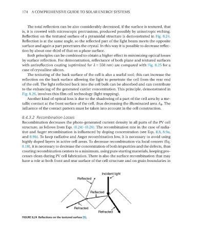
The total reflection can be also considerably decreased, if the surface is textured, that
is, it is covered with microscopic protrusions, produced possibly by anisotropic etching.
reflection on the textured surface of a pyramidal structure is demonstrated in Fig. 8.24.
reflection is at the same angle, so the reflected part of the light beam meets the opposite
surface and again a part penetrates the crystal. In this way it is possible to decrease reflec-
tion by about one-third of that on a plane surface.
Both principles can be combined to obtain a higher effect in minimizing optical losses
by surface reflection. For demonstration, reflectance of both plane and textured surfaces
with antireflection coating (optimized for λ = 550 nm) are compared with Fig. 8.25 for a
case of crystalline silicon.
The texturing of the back surface of the cell is also a useful tool; this can increase the
reflection on the back surface allowing the light to penetrate the cell from the rear end
of the cell. The light reflected back into the cell bulk can be absorbed and can contribute
to the enhancing of the generated carrier concentration. This principle, demonstrated in
Fig. 8.26, involves thin film cell technology (light trapping).
Another kind of optical loss is due to the shadowing of a part of the cell area by a me-
tallic contact at the front surface of the cell, thus decreasing the illuminated area A ill . The
influence of the contact pattern must be taken into account in the cell construction.
8.4.3.2 Recombination Losses
recombination decreases the photo-generated current density in all parts of the PV cell
structure, as follows from eqs. (8.24)–(8.26). The recombination rate in the case of radia-
tive and Auger recombination is influenced by doping concentration (see eqs. 8.8, 8.9a,
and 8.9b). To keep radiative and Auger recombination low, it is necessary to avoid using
highly doped layers in active cell areas. To decrease recombination via local centers (eq.
8.10), it is necessary to decrease the concentration of both impurities and the defects, thus
creating recombination centers to a minimum, using pure starting materials, keeping pro-
cesses clean during PV cell fabrication. There is also the surface recombination that may
have a role at both front and rear surface of the cell structure and on grain boundaries in
FIGURE 8.24 Reflections on the textured surface [5].