
Page 300 - A Comprehensive Guide to Solar Energy Systems
P. 300
304 A ComPreHenSIVe GuIde To SolAr enerGy SySTemS
14.3.1 Design and Manufacture of the Novel FGM Panel
The details of design and fabrication procedure of the FGm panel can be found in ref.
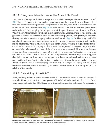
[30]. The FGm panel with embedded water tubes was fabricated by a combined vibra-
tion and sedimentation approach. The purpose of the designed double serpentine shape
of the water tubes as shown in Fig. 14.5A is to remove the heat within the panel more
uniformly and thus keeping the temperature of the panel surface much more uniform.
When the FGm panel was cured and taken out from the vacuum oven, it was seamlessly
glued to a structural substrate, such as fire-retardant plywood, or lightweight concrete
through a moisture resistant epoxy adhesive as shown in Fig. 14.5B. The integrated FGm
panel and substrate were then sprayed by a thin-layer of moisture resistant resin, which
reacts chemically with the natural moisture in the wood, creating a highly moisture re-
sistant substance similar to polyurethane. due to the gradual change of the proportion
of materials, only a small amount of aluminum powder is needed. This reduces the cost
of the panel, as the aluminum material is relatively expensive. The heat absorbing layer
and insulation layer in traditional PVTs can be replaced by one FGm layer that integrates
the high thermal conductivity in the top part and low thermal conductivity in the lower
part. As the volume fraction of aluminum particles continuously varies in the thickness
direction, the thermomechanical property distribution changes smoothly, and avoids the
thermal stress concentration across layers and increases the structural integrity and du-
rability of the panels.
14.3.2 Assembling of the BIPVT
After polishing the metal rich surface of the FGm, 16 monocrystalline silicon PV cells (with
a rated efficiency of 18.8% and rated power of 2.88 W) with dimensions of 127 × 127 mm
were mounted onto the FGm layer by a thermal conductive adhesive. To generate a
FIGURE 14.5 Embedment of water tube and integration of substrate. (A) Double serpentine shape of water tubes in
the casting mold, and (B) assembling of FGM panel with structural substrate.