
Page 301 - A Comprehensive Guide to Solar Energy Systems
P. 301
Chapter 14 • Advanced Building Integrated Photovoltaic/Thermal Technologies 305
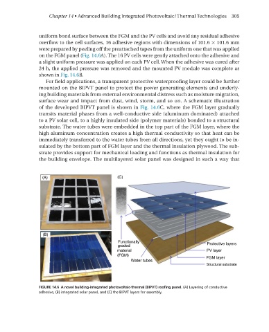
uniform bond surface between the FGm and the PV cells and avoid any residual adhesive
overflow to the cell surfaces, 16 adhesive regions with dimensions of 101.6 × 101.6 mm
were prepared by peeling off the preattached tapes from the uniform one that was applied
on the FGm panel (Fig. 14.6A). The 16 PV cells were gently attached onto the adhesive and
a slight uniform pressure was applied on each PV cell. When the adhesive was cured after
24 h, the applied pressure was removed and the mounted PV module was complete as
shown in Fig. 14.6B.
For field applications, a transparent protective waterproofing layer could be further
mounted on the BIPVT panel to protect the power generating elements and underly-
ing building materials from external environmental distress such as moisture migration,
surface wear and impact from dust, wind, storm, and so on. A schematic illustration
of the developed BIPVT panel is shown in Fig. 14.6C, where the FGm layer gradually
transits material phases from a well-conductive side (aluminum dominated) attached
to a PV solar cell, to a highly insulated side (polymer materials) bonded to a structural
substrate. The water tubes were embedded in the top part of the FGm layer, where the
high aluminum concentration creates a high thermal conductivity so that heat can be
immediately transferred to the water tubes from all directions, yet they ought to be in-
sulated by the bottom part of FGm layer and the thermal insulation plywood. The sub-
strate provides support for mechanical loading and functions as thermal insulation for
the building envelope. The multilayered solar panel was designed in such a way that
FIGURE 14.6 A novel building-integrated photovoltaic-thermal (BIPVT) roofing panel. (A) Layering of conductive
adhesive, (B) integrated solar panel, and (C) the BIPVT layers for assembly.