
Page 307 - A Comprehensive Guide to Solar Energy Systems
P. 307
Chapter 14 • Advanced Building Integrated Photovoltaic/Thermal Technologies 311
η thermal = Q water = Q water (14.2)
E IN I R ⋅ A ηthermal=QwaterEIn=QwaterIR⋅A
where E IN = I R ⋅ A is the absorbed irradiance by the BIPVT panel, which is the product of the EIn=IR⋅A
2
irradiance intensity ( I R ) and the total area of the BIPVT panel and the frame. A = 0.28 m IR
(508 × 558.8 mm) for the prototype BIPVT panel in this study. It should be mentioned that
the thermal efficiency defined in eq. (14.2) does not take into account the energy required
to pump the water into the panel; this required energy is also not accounted for in the
definition of the electric efficiency.
14.4.3 Estimation of Electricity Generation
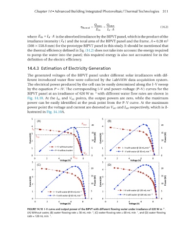
The generated voltages of the BIPVT panel under different solar irradiances with dif-
ferent introduced water flow were collected by the labVIeW data acquisition system.
The electrical power produced by the cell can be easily determined along the I–V sweep
by the equation P = IV. The corresponding I–V and power–voltage (P–V) curves for the
−2
BIPVT panel at an irradiance of 620 W m with different water flow rates are shown in
Fig. 14.10. At the I SC and V oC points, the output powers are zero, while the maximum
power can be easily identified at the peak point from the P–V curve. At the maximum
power point the voltage and current are denoted as V mP and I mP respectively, which is il-
lustrated in Fig. 14.10A.
−2
FIGURE 14.10 I–V curve and output power of the BIPVT with different flowing water under irradiance of 620 W m .
−1
(A) Without water, (B) water flowing rate = 30 mL min , (C) water flowing rate = 60 mL min , and (D) water flowing
−1
−1
rate = 120 mL min .