
Page 333 - A Comprehensive Guide to Solar Energy Systems
P. 333
338 A CoMPreheNSIVe GuIDe To SolAr eNerGy SySTeMS
the temperature increases the open-circuit voltage (hence V MPP ) decreases (Fig. 16.4B),
resulting in a significant decrease of P Max (Fig. 16.4D). ultimately, the converter aims to
follow the P max of a PV panel under varying irradiances and temperatures. Practically, the
converter/load combination constantly re-adjusts the total load seen from the PV panel
to deliver the maximum power. This load adjustment (manipulation) to follow the P Max is
known as maximum power point tracking (MPPT). Note that in a grid-connected inverter
system the load adjustment means changing the amount of current injected into the grid
through the inverter while obtaining maximum power from the PV arrays.
It should be noted here, that in practice, MPPT is achieved using various control algo-
rithms and voltage and current feedback signals. Although the complexity and effective-
ness of control algorithms may vary, the primary aim of an algorithm together with auxil-
iary systems is to reach to the P Max value in a shortest time to accommodate the variations
in irradiance and temperature.
16.3 Features of Converter Topologies in PV Systems
16.3.1 Electrical Requirements of Grid-Tied Inverters
PV systems should not only deliver maximum available power to loads for better utiliza-
tion, but should also offer quality power (ideally constant magnitude and frequency si-
nusoidal voltage and/or current waveforms). In small-scale grid-tied PV inverters, since
power electronic circuits cannot offer ideal voltage and current waveforms, this is mea-
sured by two quantities (1) the total harmonic distortion (ThD) and (2) power factor (PF).
Due to the influx of the low voltage grid-tied small-scale inverters in recent years, specific
standards have also been developed around the world. For example, in Australia (as of 2016), a
typical residential PV system is governed by the requirements as set out by AS/NZS 4777.2 [2].
As in other standards, this standard also defines the acceptable limits on ThD and PF,
which are 5%, and 0.95 (leading or lagging) within 25–100% of rated power, respectively.
Note that the level of PF is defined under a steady power output, grid voltage and grid fre-
quency and translates to a voltage–current phase angle of about 18.2°.
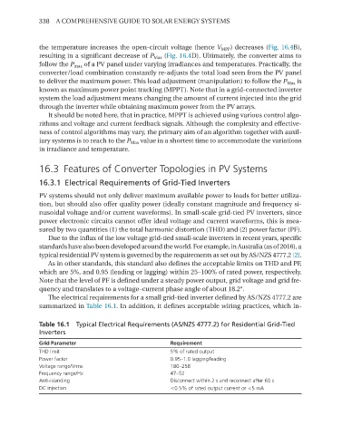
The electrical requirements for a small grid-tied inverter defined by AS/NZS 4777.2 are
summarized in Table 16.1. In addition, it defines acceptable wiring practices, which in-
Table 16.1 Typical Electrical Requirements (AS/NZS 4777.2) for Residential Grid-Tied
Inverters
Grid Parameter Requirement
THD limit 5% of rated output
Power factor 0.95–1.0 lagging/leading
Voltage range/Vrms 180–258
Frequency range/Hz 47–52
Anti-islanding Disconnect within 2 s and reconnect after 60 s
DC injection <0.5% of rated output current or <5 mA