
Page 335 - A Comprehensive Guide to Solar Energy Systems
P. 335
340 A CoMPreheNSIVe GuIDe To SolAr eNerGy SySTeMS
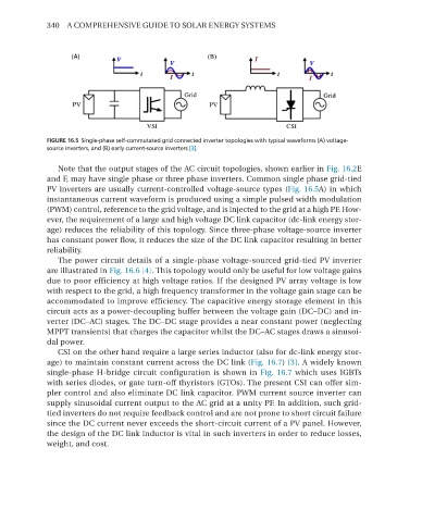
FIGURE 16.5 Single-phase self-commutated grid connected inverter topologies with typical waveforms (A) voltage-
source inverters, and (B) early current-source inverters [3].
Note that the output stages of the AC circuit topologies, shown earlier in Fig. 16.2e
and F, may have single phase or three phase inverters. Common single phase grid-tied
PV inverters are usually current-controlled voltage-source types (Fig. 16.5A) in which
instantaneous current waveform is produced using a simple pulsed width modulation
(PWM) control, reference to the grid voltage, and is injected to the grid at a high PF. how-
ever, the requirement of a large and high voltage DC link capacitor (dc-link energy stor-
age) reduces the reliability of this topology. Since three-phase voltage-source inverter
has constant power flow, it reduces the size of the DC link capacitor resulting in better
reliability.
The power circuit details of a single-phase voltage-sourced grid-tied PV inverter
are illustrated in Fig. 16.6 [4]. This topology would only be useful for low voltage gains
due to poor efficiency at high voltage ratios. If the designed PV array voltage is low
with respect to the grid, a high frequency transformer in the voltage gain stage can be
accommodated to improve efficiency. The capacitive energy storage element in this
circuit acts as a power-decoupling buffer between the voltage gain (DC–DC) and in-
verter (DC–AC) stages. The DC–DC stage provides a near constant power (neglecting
MPPT transients) that charges the capacitor whilst the DC–AC stages draws a sinusoi-
dal power.
CSI on the other hand require a large series inductor (also for dc-link energy stor-
age) to maintain constant current across the DC link (Fig. 16.7) [3]. A widely known
single-phase h-bridge circuit configuration is shown in Fig. 16.7 which uses IGBTs
with series diodes, or gate turn-off thyristors (GTos). The present CSI can offer sim-
pler control and also eliminate DC link capacitor. PWM current source inverter can
supply sinusoidal current output to the AC grid at a unity PF. In addition, such grid-
tied inverters do not require feedback control and are not prone to short circuit failure
since the DC current never exceeds the short-circuit current of a PV panel. however,
the design of the DC link inductor is vital in such inverters in order to reduce losses,
weight, and cost.