
Page 84 - Hybrid Enhanced Oil Recovery Using Smart Waterflooding
P. 84
76 Hybrid Enhanced Oil Recovery using Smart Waterflooding
also concluded that the hybrid LSPF is effective to different salinity conditions, it carried out single-
recover heavy oil from carbonate reservoirs. aqueous phase displacement experiment without
As well as the benefits and synergies underlying considering oleic phase. The same polymeric solutions
LSPF, it is necessary to investigate another potential of the conventional polymer flood and LSPF are used
risk of LSPF. Another study (AlSofi, Wang, & Kaidar, as previous studies (AlSofi et al., 2016; AlSofi, Wang,
2018) from the same research group analyzed the injec- & AlBoqmi, 2018). The single-phase coreflooding is
tivity and polymer retention of LSPF at the dynamic designed with two cycles of low salinity and high
condition. The ionic composition of low-salinity water salinity conditions. Each cycle is composed of the three
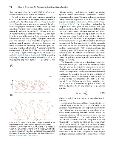
potentially expands the adsorbed polymer molecular injection phases: water, polymeric solution, and water.
and controls the level of retention (Fig. 4.9). The injec- With the injection design, the experiment consists of
tivity is the crucial factor at wellbore region and highly the four sets of coreflooding: two sets for injectivity
influences the injecting capacity of polymer EOR pro- analysis and additional two sets for polymer retention
cess. The retention is also related to the polymer loss and/or acceleration analysis. Measuring the differential
and unexpected transport of polymer. Therefore, this pressure with the flow rate, injectivity of the process is
study evaluated the injectivity, inaccessible pore vol- calculated for the two coreflooding tests. Incorporating
ume, and retention of hybrid LSPF compared with the the total organic carbon (TOC) measurements and gas
conventional polymer flood. The experimental system chromatography (GC) measuring polymer and tracer
of the study is equal to that of previous studies (AlSofi concentrations, the effluent concentration data from
et al., 2016; AlSofi, Wang, & AlBoqmi, 2018), neglecting the additional two coreflooding tests are analyzed to es-
the heavy oil flow. Because the study made an effort on timate the polymer retention/acceleration and inacces-
investigating the flow behavior of polymer at the sible pore volume.
The injectivity test of polymer flood determines the
resistance factor (R F ) and residual resistance factor
(A)
(R RF ) to analyze the injectivity quantitatively. At the
high injection rate indicating near wellbore region con-
dition, the usage of low-salinity water for makeup brine
introduces the negative impact on the injectivity of
polymer and chase water increasing both resistance fac-
R pore
tor and residual resistance factor. In addition, the rela-
tion of Eq. (4.10) between the factors calculates the
in situ viscosity of conventional polymer flood and
Ɛ H
LSPF to describe the in situ rheology of polymeric
solution.
R F
h in situ ¼ m w (4.10)
(B) R RF
where h in situ indicates the in situ viscosity of polymeric
solution.
Switching the flow rate and brine type, the in situ vis-
cosity changes as shown in Fig. 4.10. The variation in
R pore
the in situ viscosity implies that all polymeric solutions
using high-salinity injecting water or low-salinity water
Ɛ H
suffer shear-thickening behavior, which shows an
increasing viscosity with an increase in shear rate. An
interesting observation is less in situ viscosity for the
low-salinity polymeric solution compared with the
FIG. 4.9 Thickness of adsorbed polymer molecular at (A) high-salinity polymeric solution at the same shear
high-salinity water condition and (B) low-salinity water rate. Conventionally, the apparent viscosity of poly-
condition. (Credit: From AlSofi, A. M., Wang, J., & Kaidar, Z. meric solution should increase at the low salinity condi-
F. (2018b). SmartWater synergy with chemical EOR: Effects tion improving chemical stability. However, the
on polymer injectivity, retention and acceleration. Journal of experimental results show the opposite trend despite
Petroleum Science and Engineering, 166, 274e282. https:// the higher chemical stability of polymer. This opposite
doi.org/10.1016/j.petrol.2018.02.036.)