
Page 89 - Hybrid Enhanced Oil Recovery Using Smart Waterflooding
P. 89
CHAPTER 4 Hybrid Chemical EOR Using Low-Salinity and Smart Waterflood 81
(A) HSP (with HS brine)- single phase
1 Tracer - run 1 HSP, 0.23 PV
C/ Co ( Viscosity, polymer and tracer concentration) 0.7 Viscosity - run 1 HSP, 0.35 PV
0.9
Tracer - run 2
Polymer concentration - run 1
0.8
Polymer concentration - run 2
Viscosity - run 2
0.6
0.5
0.4
0.3
0.2
0.1
0
0.0 0.2 0.4 0.6 0.8 1.0 1.2 1.4 1.6 1.8 2.0
PV Injected
(B) LSP (with LS10x, tracer brine) - single phase
1 Tracer - run 1 LSP, 0.20 PV
C/ Co ( Viscosity, polymer and tracer concentration) 0.7 Viscosity - run 1 LSP, 0.05 PV
Tracer - run 2
0.9
Polymer concentration - run 1
0.8
Polymer concentration - run 2
Viscosity - run 2
0.6
0.5
0.4
0.3
0.2
0.1
0
0.0 0.2 0.4 0.6 0.8 1.0 1.2 1.4 1.6 1.8 2.0
PV Injected
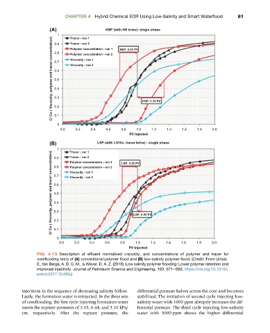
FIG. 4.13 Description of effluent normalized viscosity, and concentrations of polymer and tracer for
coreflooding tests of (A) conventional polymer flood and (B) low-salinity polymer flood. (Credit: From Unsal,
E., ten Berge, A. B. G. M., & Wever, D. A. Z. (2018). Low salinity polymer flooding: Lower polymer retention and
improved injectivity. Journal of Petroleum Science and Engineering, 163, 671e682. https://doi.org/10.1016/j.
petrol.2017.10.069.)
injections in the sequence of decreasing salinity follow. differential pressure halves across the core and becomes
Lastly, the formation water is reinjected. In the three sets stabilized. The initiation of second cycle injecting low-
of coreflooding, the first cycle injecting formation water salinity water with 1000 ppm abruptly increases the dif-
meets the rupture pressures of 5.03, 6.44, and 3.10 kPa/ ferential pressure. The third cycle injecting low-salinity
cm, respectively. After the rupture pressure, the water with 5000 ppm shows the higher differential